1
l.OOV
.&7
-3oog
lOOZ/
fE
RUI
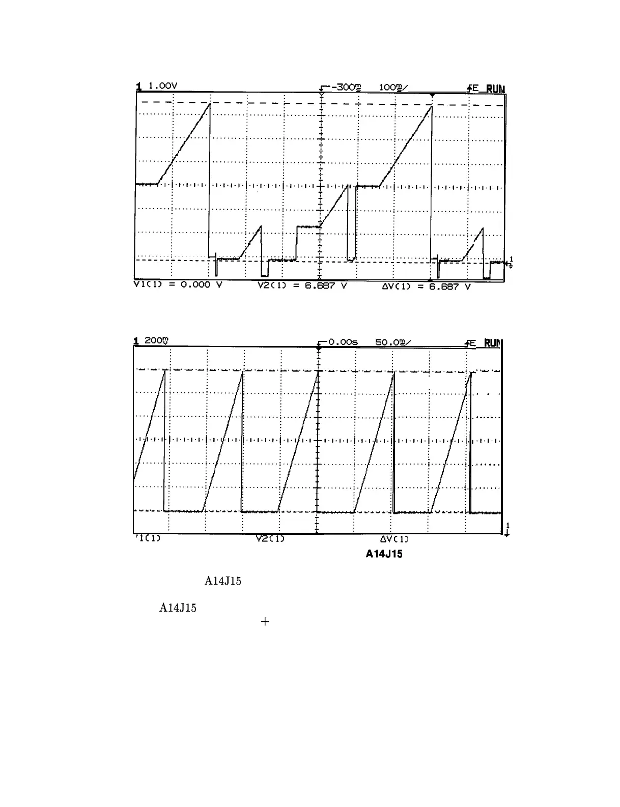
Figure 12-4. HP 8582E Rear-Panel LO SWP Output
...... ..i
..........
......
..j
.......
.j
,.,.,.,.~.,.,
.
.,.i
4
........
.
.........
.
...... ..i
..
......
.
.
“...--.a
i
JjuJ
..-.a
.
.
.
.
.
.
.
.
.
.
.,.I.,.
. . . .
.
.
,......
‘1111
= 1.456 V
V2Cl)
= 2.656 V
AVClI
= 1.200 v
Figure 12-5. HP 8582E Signal at A14J15 Pin 1
9. Check the voltage at A14J15 pin 3 with the spectrum analyzer center frequency set to
the frequencies listed in Table 12-4. The following table lists the voltage that should be
measured at A14J15 pin 3, the settings for the three switches (U416 in function block Q),
and the gain through the Sweep
+
Tune Multiplier.
12-14 RF Section