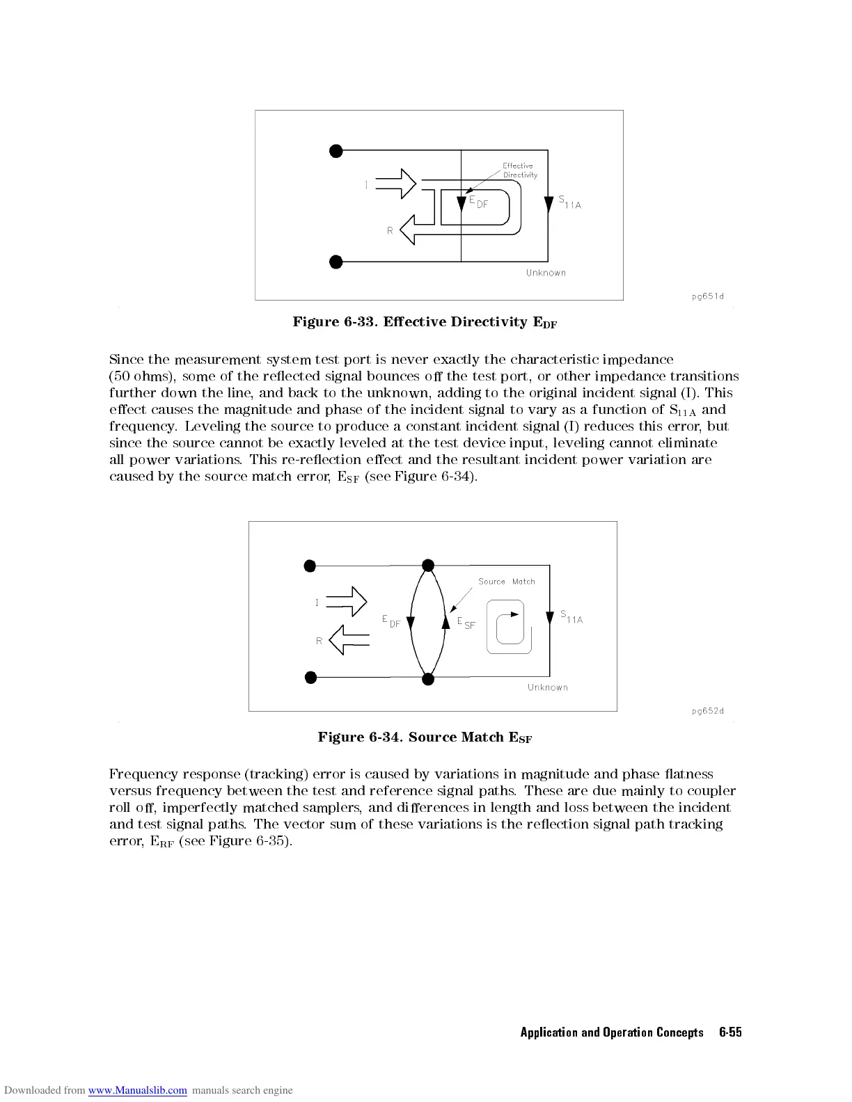
Figure
6-33.
Eective
Directivity
E
DF
Since
the
measurement
system
test
port
is
never
exactly
the characteristic
impedance
(50
ohms),
some
of
the
reected
signal
bounces
o
the
test
port, or
other impedance
transitions
further
down
the
line
,
and
back
to
the
unknown,
adding
to
the
original
incident
signal
(I).
This
eect
causes
the
magnitude
and
phase
of
the
incident
signal
to
vary
as
a
function
of
S
11A
and
frequency
.
Leveling
the
source
to produce
a constant
incident signal
(I)
reduces
this
error
,
but
since
the
source
cannot
be
exactly leveled
at the
test device
input, leveling
cannot
eliminate
all
power
variations
.
This
re-reection
eect
and the
resultant incident
power
variation
are
caused
by
the
source
match
error
,
E
SF
(see
Figure
6-34
).
Figure
6-34.
Source
Match
E
SF
Frequency
response (tracking) error is caused by variations in magnitude and phase atness
versus frequency
between the test and reference signal paths
. These are due mainly to coupler
roll o,
imperfectly matched samplers
, and dierences in length and loss between the incident
and test signal
paths. The vector sum of these variations is the reection signal path tracking
error,E
RF
(see Figure 6-35).
Application and Operation Concepts 6-55