Rear P
anel F
eatures and
Connectors
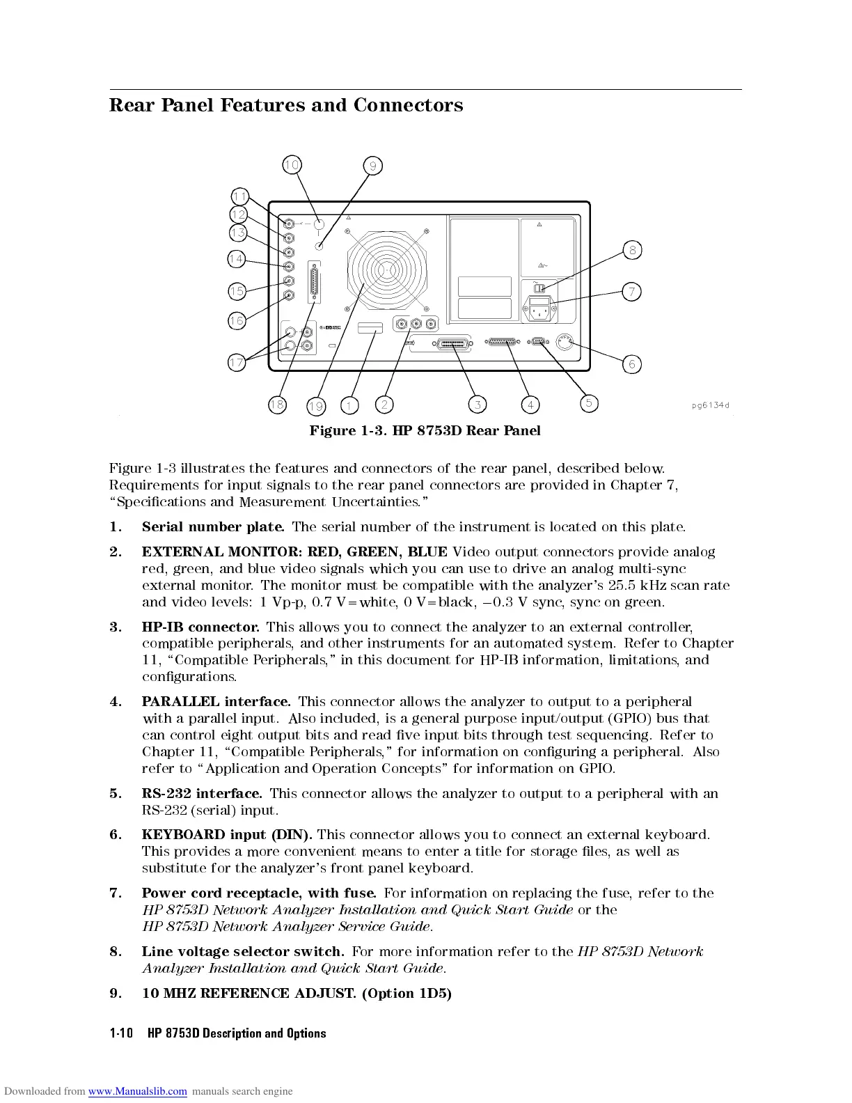
Figure
1-3.
HP
8753D
Rear
P
anel
Figure
1-3
illustrates
the
features
and
connectors
of
the
rear
panel,
described
below
.
Requirements
for
input
signals
to
the
rear
panel
connectors
are
provided
in
Chapter
7,
\Specications
and
Measurement
Uncertainties
."
1.
Serial
number
plate
.
The
serial
number
of
the
instrument
is
located
on
this
plate
.
2.
EXTERNAL
MONITOR:
RED
,
GREEN,
BLUE
Video
output
connectors
provide
analog
red,
green,
and
blue
video
signals
which
you
can
use
to
drive an
analog
multi-sync
external
monitor
.
The
monitor
must
be
compatible
with
the
analyzer's
25.5 kHz
scan
rate
and
video
levels:
1
Vp-p
,
0.7
V=white
,
0
V=black,
0
0.3
Vsync
,
sync
on
green.
3.
HP-IB
connector
.
This
allows
you
to
connect
the
analyzer
to an
external controller
,
compatible
peripherals,
and other
instruments for
an automated
system.
Refer
to
Chapter
11,
\Compatible
P
eripherals,"
in this
document for
HP-IB
information,
limitations
,
and
congurations
.
4.
P
ARALLEL
interface.
This connector
allows the
analyzer to
output
to
a
peripheral
with
a
parallel
input. Also
included, is
a general
purpose input/output
(GPIO)
bus
that
can
control eight
output bits
and read
ve
input
bits
through
test
sequencing.
Refer
to
Chapter
11,
\Compatible
P
eripherals
," for
information
on
conguring
a
peripheral.
Also
refer to \Application and Operation Concepts"
for information on GPIO
.
5. RS-232 interface
.
This connector allows
the analyzer to output to a peripheral with an
RS-232 (serial) input.
6. KEYBOARD input (DIN).
This connector allows you to connect an external keyboard.
This provides a more convenient means to enter a title for storage les
, as well as
substitute for the analyzer's front panel keyboard.
7. Power cord receptacle, with fuse.
For information on replacing the fuse, refer to the
HP 8753D Network Analyzer Installation and Quick Start Guide
or the
HP 8753D Network Analyzer Service Guide
.
8. Line voltage selector switch.
For more information refer to the
HP 8753D Network
Analyzer Installation and Quick Start Guide
.
9. 10 MHZ REFERENCE ADJUST. (Option 1D5)
1-10 HP 8753D Description and Options