Model
8903B
Source
Frequency
(H4
91
20
4560
2280
1140
570
285
142.5
Table
8B-10.
Amplitude Limits
on
Display,
(J2)
Step 7
Amplitude Limits
(%)
Special
Functions Minimum Maximum
54.128, 54.127 97 99
54.64, 54.63 94 97
54.32, 54.31 90 94
54.16, 54.15 82 88
54.8, 54.7 68 76
54.4, 54.3 46 58
54.2, 54.1 20 40
Special
Function
53.0
53.1
53.2
53.3
Source
Frequency
(H4
98.7
49.4
197
781
390
1
560
6 250
3 130
12
500
50
000
25
000
100
000
Amplitu
Minimum
2.8V
15%
15%
2.8V
15%
15%
2.8V
15%
15%
2.8V
15%
15%
!
Limits
Maximum
3.2V
25%
25%
3.2V
25%
25%
3.2V
25%
25%
3.2V
25%
25%
Table
8B-11.
Amplitude Limits
on
Display,
@)
Step
8
Service
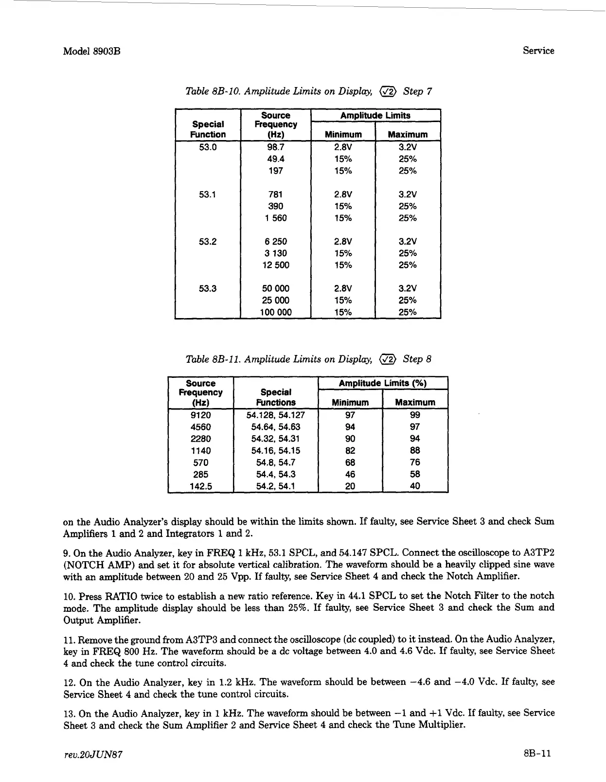
on the Audio Analyzer’s display should be within the limits shown.
If
faulty, see Service Sheet 3 and check Sum
Amplifiers 1 and 2 and Integrators 1 and
2.
9.
On the Audio Analyzer, key in
FREQ
1
kHz, 53.1 SPCL, and 54.147
SPCL.
Connect the oscilloscope to A3TP2
(NOTCH AMP) and set
it
for absolute vertical calibration. The waveform should
be
a
heavily clipped sine wave
with an amplitude between
20
and 25 Vpp.
If
faulty, see Service Sheet 4 and check the Notch Amplifier.
10. Press RATIO twice to establish a new ratio reference. Key
in
44.1 SPCL
to
set the Notch Filter to the notch
mode. The amplitude display should be less than
25%.
If
faulty, see Service Sheet 3 and check the
Sum
and
Output Amplifier.
11. Remove the ground from A3TP3 and connect the oscilloscope (dc coupled)
to
it
instead. On the Audio Analyzer,
key in
FREQ
800
Hz.
The waveform should be
a
dc voltage between
4.0
and 4.6 Vdc.
If
faulty, see Service Sheet
4
and check the tune control circuits.
12.
On the Audio Analyzer, key in 1.2 kHz. The waveform should be between -4.6 and
-4.0
Vdc.
If
faulty,
see
Service Sheet
4
and check the tune control circuits.
13. On the Audio Analyzer, key in
1
kHz. The waveform should be between -1 and +1 Vdc.
If
faulty, see Service
Sheet
3
and check the Sum Amplifier 2 and Service Sheet 4 and check the Tune Multiplier.
rev.20JUN87
8B-11