I
For
HP
Internal Use Only
Table
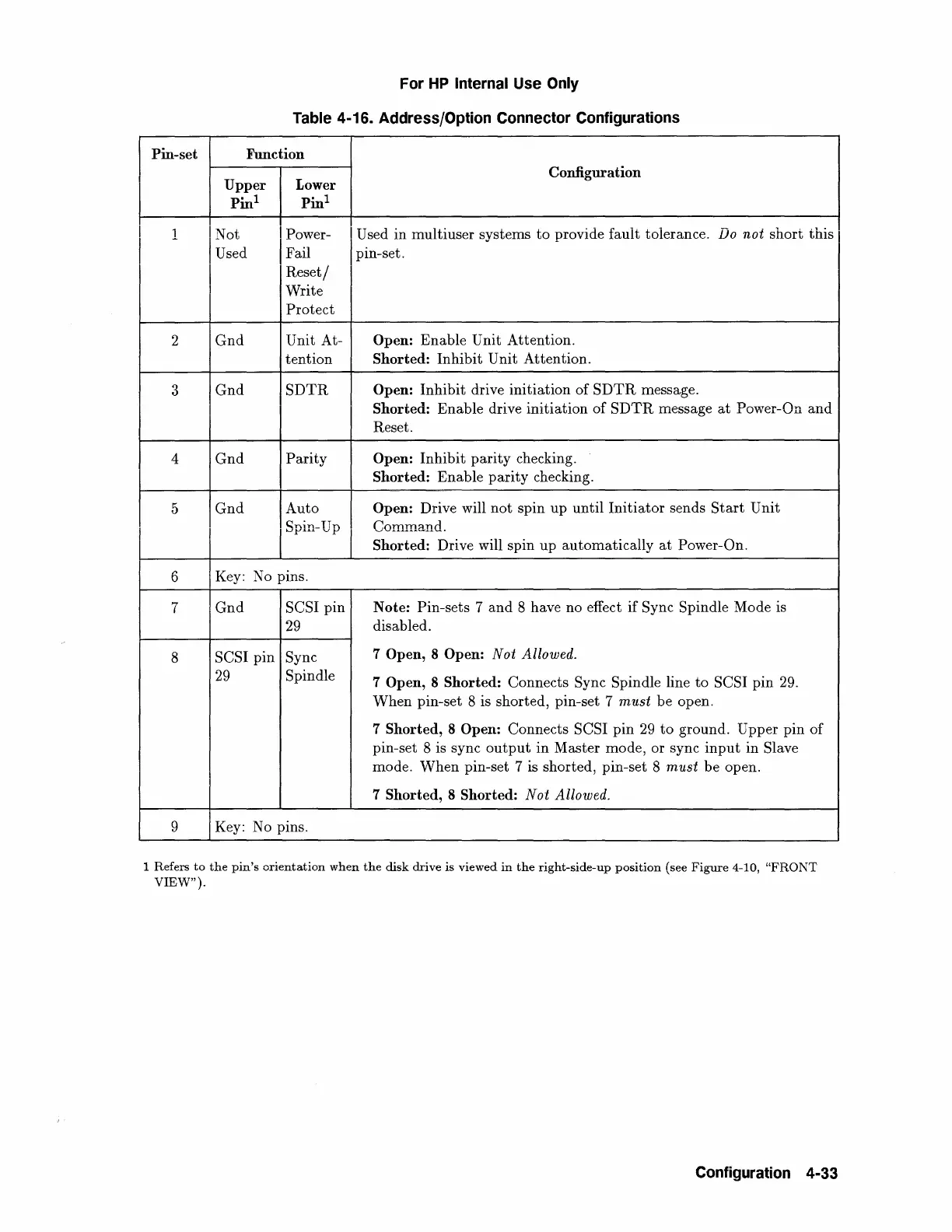
4-16. Address/Option Connector Configurations
Pin-set Function
Upper
Lower
Configuration
Pin
1
Pin
1
1
I Not
I Power-
I Used in multiuser systems
to
provide fauit tolerance. Do
noi
short
this
Used Fail
pm-set.
I
Reset/
Write
Protect
2
Gnd
Unit At-
Open: Enable Unit Attention.
tention Shorted: Inhibit Unit Attention.
3
Gnd
SDTR
Open: Inhibit drive initiation
of
SDTR
message.
Shorted: Enable drive initiation
of
SDTR
message
at
Power-On
and
Reset.
4
Gnd
Parity
Open: Inhibit
parity
checking.
Shorted: Enable
parity
checking.
5
Gnd
Auto
Open: Drive will
not
spin up until
Initiator
sends
Start
Unit
Spin-Up
Command.
Shorted: Drive will spin up automatically
at
Power-On.
6
Key:
No
pins.
7
Gnd
SCSI pin
Note: Pin-sets 7
and
8 have no effect if Sync Spindle Mode is
29
disabled.
8
SCSI pin Sync
7 Open, 8 Open:
Nat
Allowed.
29
Spindle
7 Open, 8 Shorted: Connects Sync Spindle line
to
SCSI pin
29.
When pin-set 8 is shorted, pin-set 7
must
be open.
7 Shorted, 8
Open: Connects SCSI pin
29
to
ground. Upper pin
of
pin-set 8 is sync
output
in Master mode, or sync
input
in Slave
mode.
When
pin-set 7 is shorted, pin-set 8
must
be open.
7 Shorted, 8 Shorted:
Not
Allowed.
9
Key:
No
pins.
1 Refers
to
the
pin's
orientation
when
the
disk
drive
is
viewed
in
the
right-side-up
position
(see
Figure
4-10,
"FRONT
VIEW").
Configuration 4-33
 Loading...