A4576
4-2
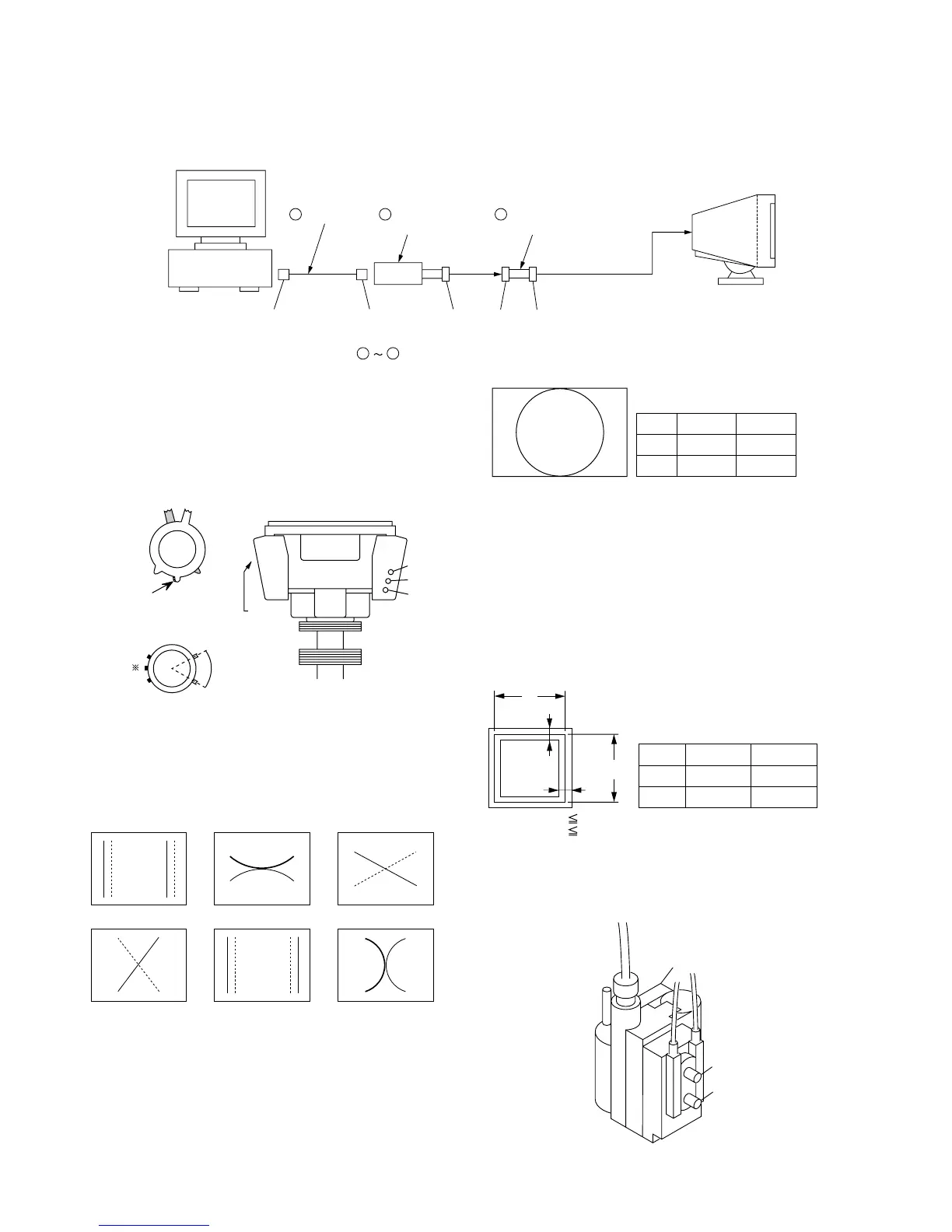
Connect the communication cable of the computer to the connector located on the D board on the monitor. Run the service software and
then follow the instruction.
• Convergence Rough Adjustment
(1) Receive an image of the white crosshatch signals (white lines
on black).
(2) Place the protrusions of the 6-fold poles magnet attached to
the CRT neck upon each other. (Fig. 1)
(3) Make rough adjustment of the H and V direction convergence
by using 4-fold poles magnet.
(4) Make a rough adjustment of the V direction convergence by
using “V. STAT”.
* Set so that the protruding parts of
the 2 magnet rings agree with each
other.
*
• Convergence Specification
• White Balance Adjustment Specification
(1) 9300K
x = 0.283 ± 0.005
y = 0.298 ± 0.005
(All White)
(2) 6500K (3) 5000K
x = 0.313 ± 0.005 x = 0.346 ± 0.005
y = 0.329 ± 0.005 y = 0.359 ± 0.005
(All White) (All White)
• Vertical and Horizontal Position and Size
Specification
• Focus adjustment
Adjust the focus volume 1 and 2 (HDK 1 and 2) for the
optimum focus.
B
a
a 3.2 mm
b 3.2 mm
a
b
b
A
MODE
A
B
1 - 5, 9 -10
388 mm
291 mm
6 - 8
364 mm
291 mm
XBV XCV
R
B
B
RR
B
B
R
BBR
H. AMP
H. TILT (TLH) YBHYCH
R B
R B
R
B
A
MODE
A
B
4 - 10
0.24 mm
0.28 mm
1 - 3
0.24 mm
0.32 mm
FBT
HDK1 (V)
HDK2 (H)
IBM AT Computer
as a Jig
1-690-391-21
1
A-1500-819-A
Interface Unit
2
*The parts above ( ) are necessary for DAS adjustment.
1
3
D-sub
(9 Pin [female])
mini Din
(8Pin)
4 Pin
3-702-691-01
Connector Attachment
3
To BUS CONNECTOR
4 Pin 4 Pin
Protrusions
60°
Fig. 1
Fig. 3
Fig. 2
TLV
YCH
YBH
XBV
XCV
APH