2
Application scenario
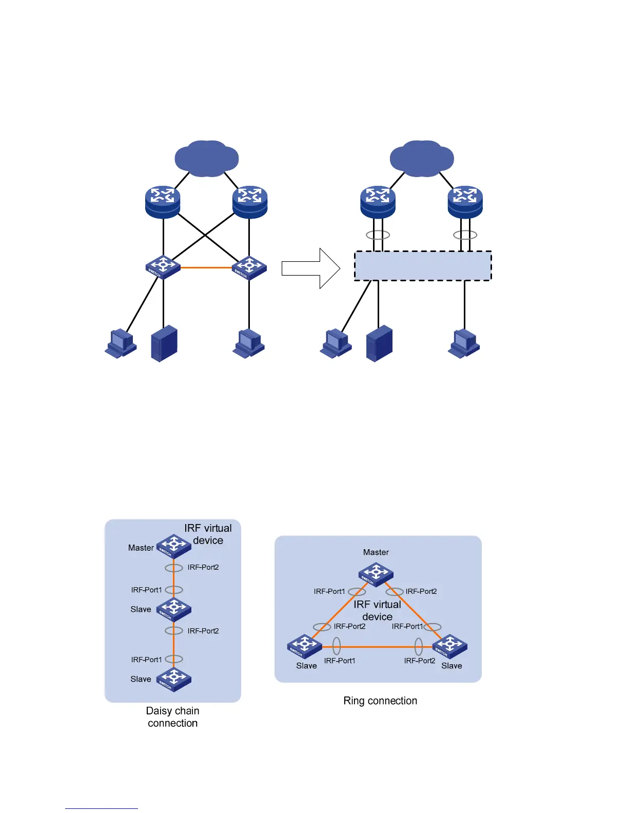
Figure 1 shows an IRF virtual device that comprises two switches, which appear as a single node to the
upper and lower layer devices.
Figure 1 IRF application scenario
IP network
IRF virtual device
IP network
IRF link
Equal to
Master
Slave
IRF topologies
Create an IRF virtual device in daisy chain topology, or more reliably, ring topology, as shown in Figure
2.
In ring chain t
opology, the failure of one IRF link does not cause the IRF virtual device to split as in daisy
chain topology. Rather, the IRF virtual device changes to a daisy chain topology without affecting
network services.
Figure 2 IRF connections
 Loading...


