Chapter 1 49
Remove/Replace System Components
Removing/Replacing System Components
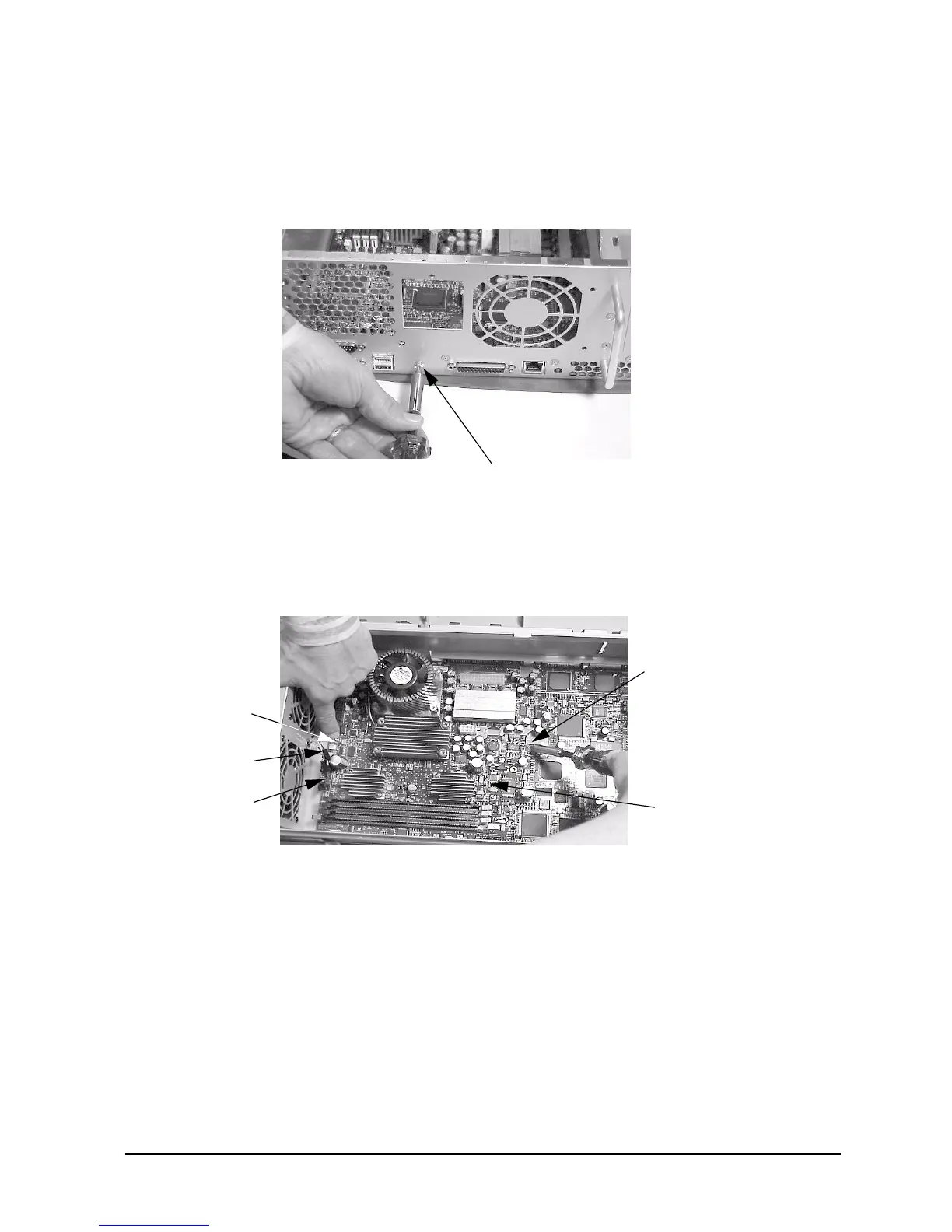
4. Align the system board screw hole that is located on the workstation’s chassis with the
threaded screw hole on the system board’s handle and screw in the system board’s rear
mounting screw. See Figure 1-59.
Figure 1-59. Screwing in the System Board’s Rear Mounting Screw
5. Connect the two fan power connectors into their connectors on the system board. The
LCD connector must also be connected into its connector on the system board. Next,
screw the two internal system board mounting screws. See Figure 1-60.
Figure 1-60. Replacing the Internal System Board Mounting Screws
6. Complete the procedure in the section “Replacing the AC or DC Power Supply”
(steps 2 through 4) found in this chapter.
7. Complete the procedure in the section “Replacing the Hard Disk Drive(s)” (steps 3
through 4) found in this chapter.
8. Complete the procedure in the section “PCI Cage Replacement” (step 2) found in
this chapter.
9. Complete the procedure in the section “Replacing the CD Drive” (steps 2 through
8; in this chapter), “Replacing the DAT Drive” (steps 2 through 7; in Appendix
C), or “Replacing the Flexible Disk Drive” (steps 2 through 9; in Appendix D).
Rear Mounting Screw
System Board
Mounting Screw
System Board
Mounting Screw
System Board
Two Fan Power
Connectors
LCD Connector
 Loading...