EasyManuals Logo

HP BENCH Series User Manual

HP BENCH Series
38 pages
To Next Page IconTo Next Page
To Previous Page IconTo Previous Page
Page #10 background imageLoading...
Page #10 background image
SECTION
III
OPERATING
INSTRUCTIONS
3-1
TURN-ON
CHECKOUT
PROCEDURE
3-5
CONSTANT
VOLTAGE
3-2
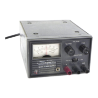
The
following
checkout
procedure
describes
the
use
of
the
front
panel
controls
and
indicators
and
ensures
that
the
supply
is
operational;
a.
Set
AC
toggle
switch
(1)
upward
to
on
position;
indicator
(2)
should
light.
VOLTS
20
30
40
10
L
L__/
50
VOLTAGE
COARSE
FINE
METER
SELECTION
vOLTS^yjUgl^mA
+
GND
Figure
3-1.
Front
Panel
Controls
and
Indicators
b.
Set
METER
SELECTION
switch
(4)
to
VOLTS
position.
c.
Turn
COARSE
(6)
and
FINE
(5)
VOLTAGE
controls
fully
ccw
to
ensure
that
output
decreases
to
OV,
then
turn
the
VOLTAGE
controls
fully
cw
to
ensure
that
output
voltage
increases
to
the
maxi
mum
rated
output
voltage.
d.
Connect
a
milliammeter
across
the
out
put
of
the
supply
(3)
to
check
that
the
current
limit
circuit
within
the
supply
is
limiting
the
out
put
current
to:
Model
Current
Limit
6213A
1300
±50mA
6215A
475
±10mA
6217A
250
±10mA
e.
Remove
milliammeter
and
connect
load
to
output
terminals.
3-3
OPERATION
3-4
The
power
supply
can
be
operated
as
a
single
unit
(normal
operation),
in
parallel,
or
in
series.
The
output
of
the
supply
can
be
floated
up
to
300
volts
off
ground.
3-6
To
select
a
constant
voltage
output
turn
on
the
supply
and,
with
no
load
connected,
adjust
the
VOLTAGE
controls
for
the
desired
output
volt
age.
To
check
the
current
limit,
connect
an
ex
ternal
ammeter
across
the
output
of
the
supply,
turn
the
VOLTAGE
controls
fully
clockwise,
and
observe
the
reading.
The
current
limit
is
factory
adjusted
in
excess
of
the
current
rating
of
the
supply.
If
the
existing
current
is
not
compatible
with
the
anticipated
load
requirements,
the
limit
can
be
changed
as
outlined
in
the
following
para
graphs.
3-7
CHANGING
CURRENT
LIMIT
3-8
The
current
limit
can
be
varied
by
adjusting
resistor
R50,
located
on
the
printed
wiring
board.
This
adjustment
procedure
is
described
in
Para
graph
5-63.
The
range
of
the
current
limit
control
R50
is
as
follows:
Model
Current
Limit
Range
6213A
800
-
1700mA
6215A
300
-
540mA
6217A
180
-
300mA
The
current
limit
is
normally
adjusted
to
a
value
far
in
excess
of
the
current
rating
of
the
supply
to
prevent
the
deterioration
of
line
and
load
regulation.
Therefore,
if
for
any
reason
the
current
limit
is
adjusted
so
that
the
output
current
is
close
to
this
value,
the
performance
will
not
meet
the
published
specifications.
3-9
CONNECTING
LOAD
3-10
Each
load
should
be
connected
to
the
power
supply
output
terminals
using
separate
pairs
of
connecting
wires.
This
will
minimize
mutual
coup
ling
effects
between
loads
and
will
retain
full
ad
vantage
of
the
low
output
impedance
of
the
power
supply.
Each
pair
of
connecting
wires
should
be
as
short
as
possible
and
twisted
or
shielded
to
re
duce
noise
pickup.
(If
shield
is
used,
connect
one
end
to
power
supply
ground
terminal
and
leave
the
other
end
unconnected.)
3-11
If
load
considerations
require
that
the
output
power
distribution
terminals
be
remotely
located
from
the
power
supply,
then
the
power
supply
out
put
terminals
should
be
connected
to
the
remote
distribution
terminals
via
a
pair
of
twisted
or
shielded
wires
and
each
load
separately
connected
3-1

Table of Contents

Questions and Answers:

Question and Answer IconNeed help?

Do you have a question about the HP BENCH Series and is the answer not in the manual?

HP BENCH Series Specifications

General IconGeneral
BrandHP
ModelBENCH Series
CategoryPower Supply
LanguageEnglish

Related product manuals