3.1 List the basic steps that should typically be followed to remove components and materials requiring selective treatment:
1. remove bottom rubber cover foot x4, screw*4, and bottom cover sub-assy.
2. remove side cover screw*2, and side cover sub-assy.
3. remove bottom shielding screw*4, pull out DC cable, and bottom shielding sub-assy.
4. remove SSD screw*1, WLAN screw*1, pull out WLAN cable, and SSD/WLAN sub-assy.
5. remove DDR shielding can, and DDR RAM sub-assy.
6. remove MB screw*4, pull out power board cable, and MB sub-assy.
7. remove Top shielding screw*4, and Top shielding sub-assy.
8. remove power board screw*2, and power board sub-assy.
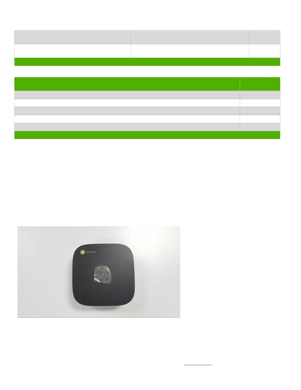
3.2 Optional Graphic. If the disassembly process is complex, insert a graphic illustration below to identify the items
contained in the product that require selective treatment (with descriptions and arrows identifying locations).
3.21 Total part disassembly
3.22 Remove bottom cover rubber, bottom cover screw and disassembly