that it is not damaged before calibrating the scanner (an old or damaged maintenance sheet may cause
this problem); if it is damaged, reprint it as explained in Calibrate the scanner (see Calibrate the scanner
on page 112).
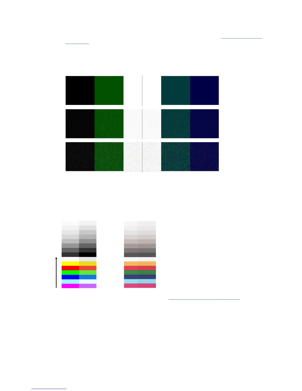
5. If the problem persists, proceed to analyze areas I and J of the diagnostic plot across modules =, 1 and 3.
In the three examples below, the top example is ideal, the middle example can be regarded as
acceptable; but, if you see something similar to the bottom example (or worse), call HP support and
report “grain in area lls”.
Small color dierences between adjacent scanbars
When scanning wide plots, sometimes slightly dierent colors can be seen at both sides of the junction
between two scanbars. This issue, if present, can be easily seen by analyzing patterns A and G of the
diagnostic plot at the intersection between scanbars. Here are some examples. Please note the black arrow
indicating the scanning direction in these examples.
Sometimes the color mismatch between adjacent modules can be enormous, showing a serious scanner
malfunction, as in the following example. If this occurs, see Completely wrong colors on page 163.
154 Chapter 17 Troubleshooting copy and scan quality issues ENWW
 Loading...

