Pinchwheel Assembly 427
Removal & Installation
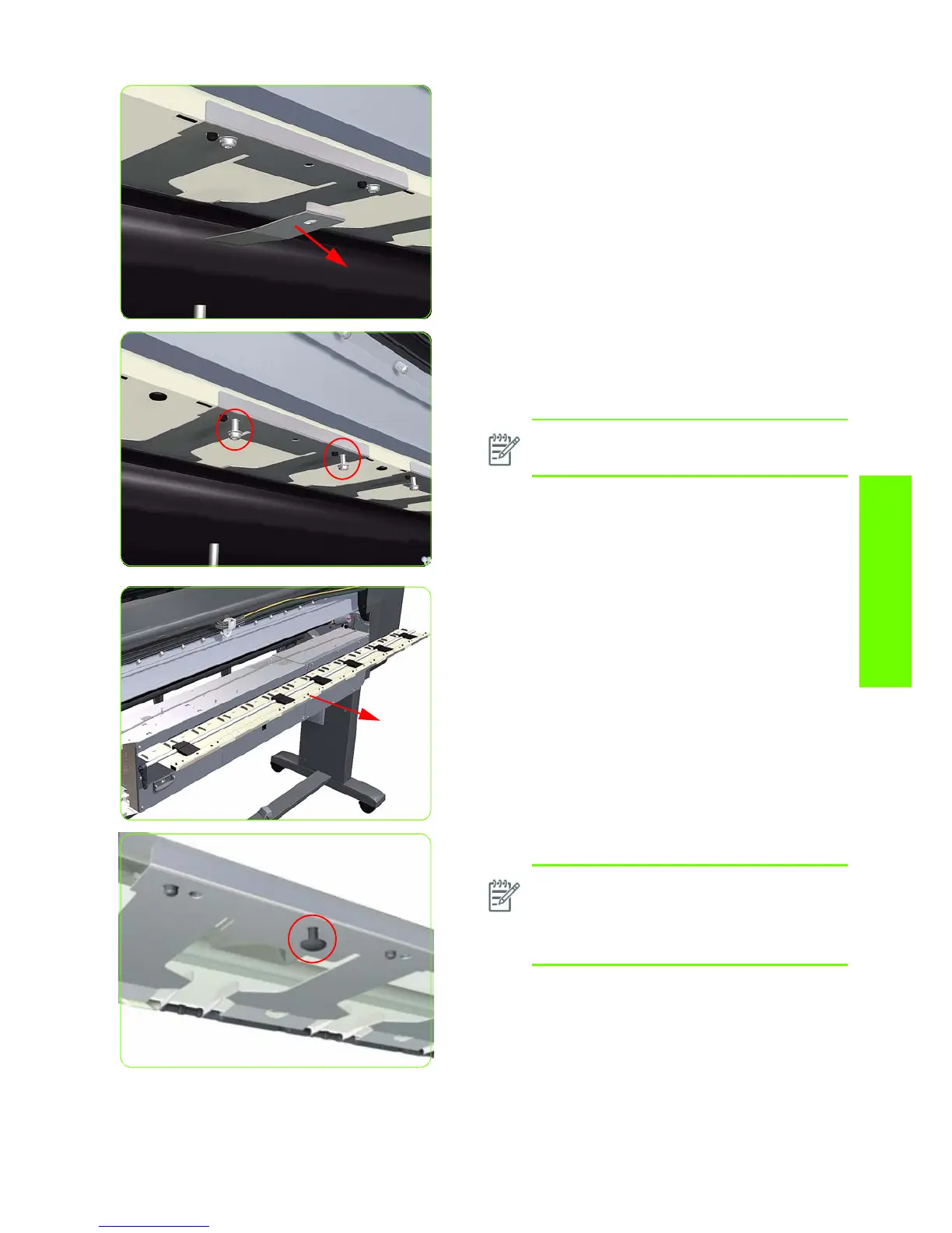
11. For the 60-inch model, remove the attachment plate
from the center Pinchwheel Subassembly.
12. Remove two T-20 screws (Type M) from each
Pinchwheel Subassembly (a 90 degree angle
screwdriver is included with the replacement
Pinchwheel Assembly).
13 . Remove the complete Pinchwheel Assembly (including
the Cam and Cam Lever) from the Printer.
NOTE: The illustration shows the 60-inch
model center Pinchwheel Subassembly.
NOTE: Before installing the NEW Pinchwheel
Assembly, insert the plastic studs in to each
Pinchwheel subassembly. This will make it
easier to install the complete Pinchwheel
Assembly.
 Loading...