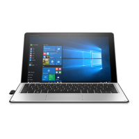
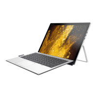
System board
Description Spare part number
System board
UMA graphics M3-6Y30 4GBx2 1012 G1 with Windows operating system 844858-601
UMA graphics M3-6Y30 4GB fWWANx2 1012 G1 with Windows operating system and WWAN capability 845470-601
UMA graphics M5-6Y54 4GBx2 1012 G1 with Windows operating system 845483-601
UMA graphics M5-6Y54 4GBx2 1012 G1 with Windows operating system and WWAN capability 845484-601
UMA graphics M5-6Y54 8GBx2 1012 G1 with Windows operating system 845485-601
UMA graphics M5-6Y54 8GBx2 1012 G1 with Windows operating system 845486-601
UMA graphics M5-6Y57 4GB fWWANx2 1012 G1 with Windows operating system and WWAN capability 845471-601
UMA graphics M5-6Y57 8GBx2 1012 G1 with Windows operating system 845472-601
UMA graphics M5-6Y578GBfWWANx2 1012 G1 with Windows operating system and WWAN capability 845473-601
UMA graphics M7-6Y758GBfWWANx2 1012 G1 with Windows operating system and WWAN capability 845474-601
Hall sensor 844874-001
IMPORTANT: Make special note of each screw and screw lock size and location during removal
and replacement.
Before removing the display panel, follow these steps:
1. Turn o the computer. If you are unsure whether the computer is o or in Hibernation, turn
the computer on, and then shut it down through the operating system.
2. Disconnect the power from the computer by unplugging the power cord from the computer.
3. Disconnect all external devices from the computer.
4. Remove the following components:
a. Keyboard (select products only) (see Keyboard (select products only) on page 29)
b. Back cover (see Back cover on page 30)
c. Display panel (see Display panel on page 31)
d. Touch controller board (see Touch controller board on page 33)
e. WLAN module (see WLAN module on page 34)
f. WWAN module (select products only) (see WWAN module (select products only) on page 36)
g. Solid-state drive (see Solid-state drive on page 38)
h. Battery (see Battery on page 42)
Remove the system board:
1. Remove the microSD tray and the micro SIM tray (1).
2. Disconnect the hall sensor (2) from the display cable.
3. Disconnect 2 speaker cables (3)
50 Chapter 5 Removal and replacement procedures for Authorized Service Provider parts
 Loading...