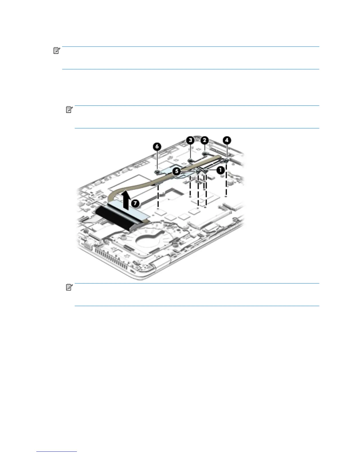
Remove the heat sink:
NOTE: Steps 1 and 2 apply to computer models equipped with graphics subsystems with discrete memory.
See steps 3 and 4 for heat sink removal information for computer models equipped with graphics
subsystems with UMA memory.
1. Following the 1, 2, 3, 4, 5, 6 sequence stamped into the heat sink, loosen the six captive Philllips screws
(1) through (6) that secure the heat sink to the system board.
2. Remove the heat sink (7).
NOTE: Due to the adhesive quality of the thermal material located between the heat sink
and the system board components, it may be necessary to move the heat sink from side to side to
detach it.
NOTE: Steps 3 and 4 apply to computer models equipped with graphics subsystems with UMA
memory. See steps 1 and 2 for heat sink removal information for computer models equipped with
graphics subsystems with discrete memory.
3. Following the 1, 2, 3, 4 sequence stamped into the heat sink, loosen the four captive Philllips screws (1)
through (4) that secure the heat sink to the system board.
ENWW Component replacement procedures 85
 Loading...