4. Remove the connector board (4) and cable.
Reverse this procedure to install the connector board.
Display assembly
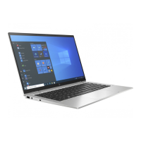
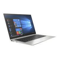
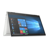
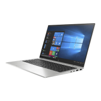
To remove and disassemble the display assembly, use these procedures and illustrations.
Table
5-6 Display assembly description and part number
Description Spare part number
Display assembly, UHD, AMOLED, 400 nits M45812-001
Display assembly, FHD, antiglare 400 nits M45810-001
Display assembly, FHD, BrightView, 400 nits M45811-001
Display assembly, FHD, antiglare, 1000 nits M45813-001
Display assembly, FHD, BrightView, 1000 nits M45814-001
Before removing the display panel, follow these steps:
1. Prepare the computer for disassembly (see Preparation for disassembly on page 35).
2. Remove the bottom cover (see Bottom cover on page 35).
3. Disconnect the battery cable from the system board (see Battery on page 36).
Remove the display assembly:
1. Remove the WWAN module shield (1).
2. Disconnect the WLAN antenna cables (2) from the WLAN module terminals.
NOTE: The #1/white WLAN antenna cable connects to the WLAN module #1/Main terminal. The #2/
black WLAN antenna cable connects to the WLAN module #2/Aux terminal.
Component replacement procedures 43

 Loading...
