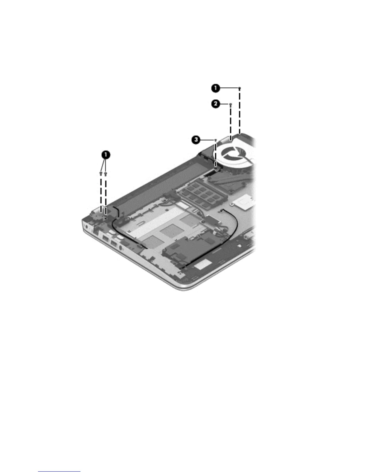
5. Remove the following screws that secure the display assembly to the top cover:
(1) Three Phillips PM2.5×4.5 screws (two on the left hinge, one on the right hinge)
(2) One Phillips PM2.5×6.5 screw on the right hinge
(3) One Phillips PM2.0×2.5 screw securing the ground loop on the right hinge
6. Open the display hinges as far as they will open (1).
Component replacement procedures 57

 Loading...