a. Remove the display back cover.
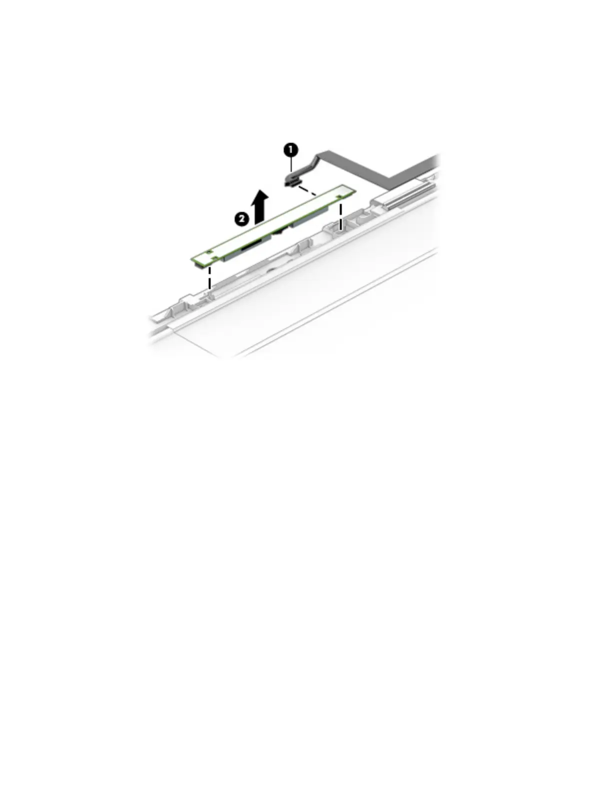
b. Disconnect the webcam/microphone module cable (1) from the webcam/microphone module.
c. Detach the webcam/microphone module (2) from the display panel assembly. (The webcam/
microphone module is attached to the display panel assembly with double-sided adhesive.)
d. Remove the webcam/microphone module.
The webcam/microphone module is available using spare part number 810961-001.
6. If it is necessary to replace the display panel cable:
a. Remove the display back cover.
b. Disconnect the webcam/microphone module cable (1) from the webcam/microphone module.
c. Disconnect the TouchScreen board cable (2) from the TouchScreen board (TouchScreen
models only).
d. Release the adhesive strip (3) that secures the display panel cable connector to the display panel.
e. Disconnect the display panel cable (4) from the display panel.
HP
Condential
Component replacement procedures 53

 Loading...