3. Remove the wireless module compartment cover.
The wireless module compartment cover is included in the Service Cover Kit, spare part number
698086-001.
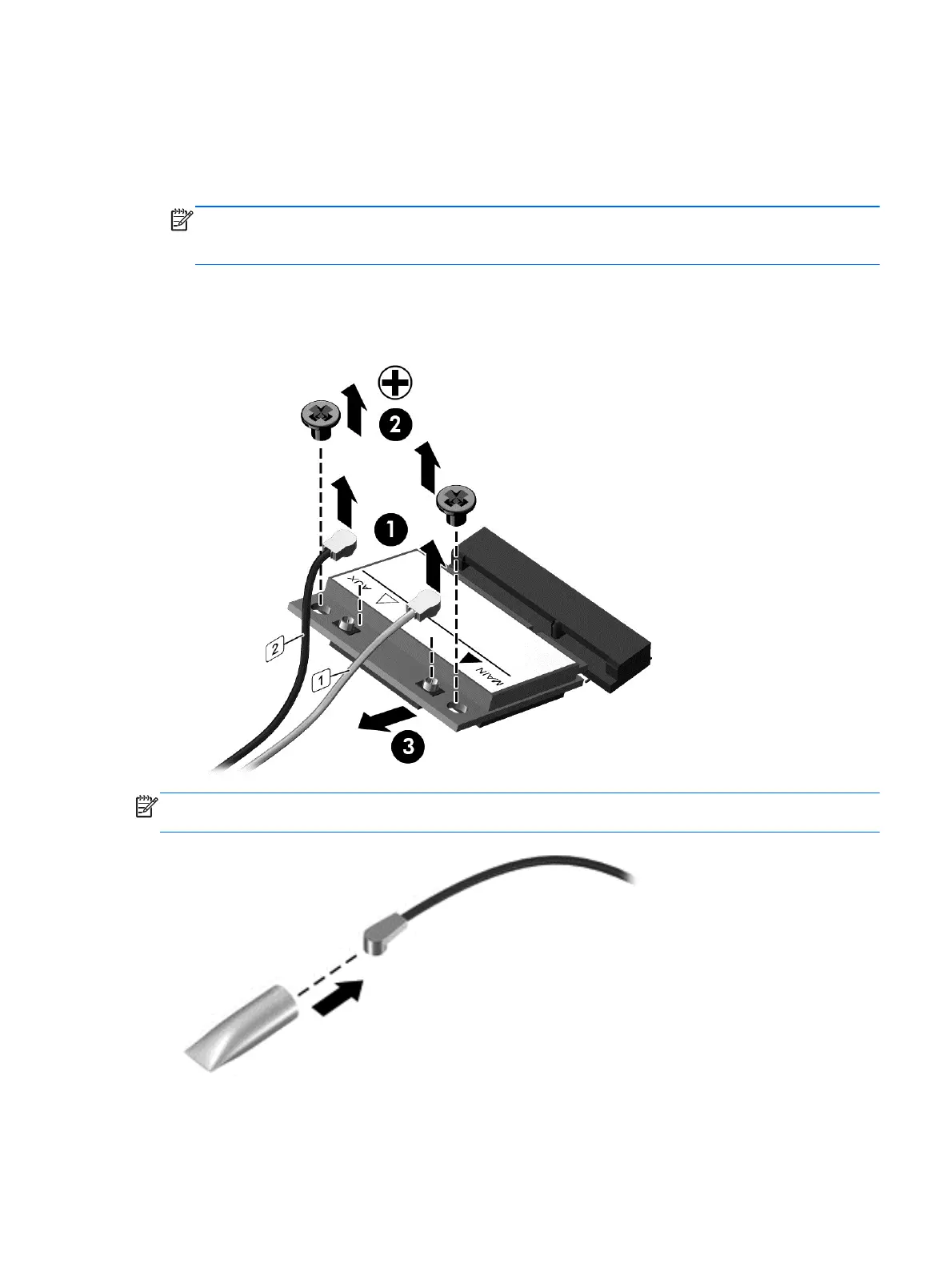
4. Disconnect the WLAN antenna cables (1) from the terminals on the WLAN module.
NOTE: The WLAN antenna cable labeled “1” connects to the WLAN module “Main” terminal
labeled “1”. The WLAN antenna cable labeled “2” connects to the WLAN module “Aux” terminal
labeled “2”.
5. Remove the two Phillips PM2.0×3.5 screws (2) that secure the WLAN module to the
base enclosure. (The WLAN module tilts up.)
6. Remove the WLAN module (3) by pulling the module away from the slot at an angle.
NOTE: If the WLAN antenna cables are not connected to the terminals on the WLAN module, the
protective sleeves must be installed on the antenna connectors, as shown in the following illustration.
Reverse this procedure to install the WLAN module.
Component replacement procedures 39
This manual downloaded from http://www.manualowl.com
 Loading...