3.
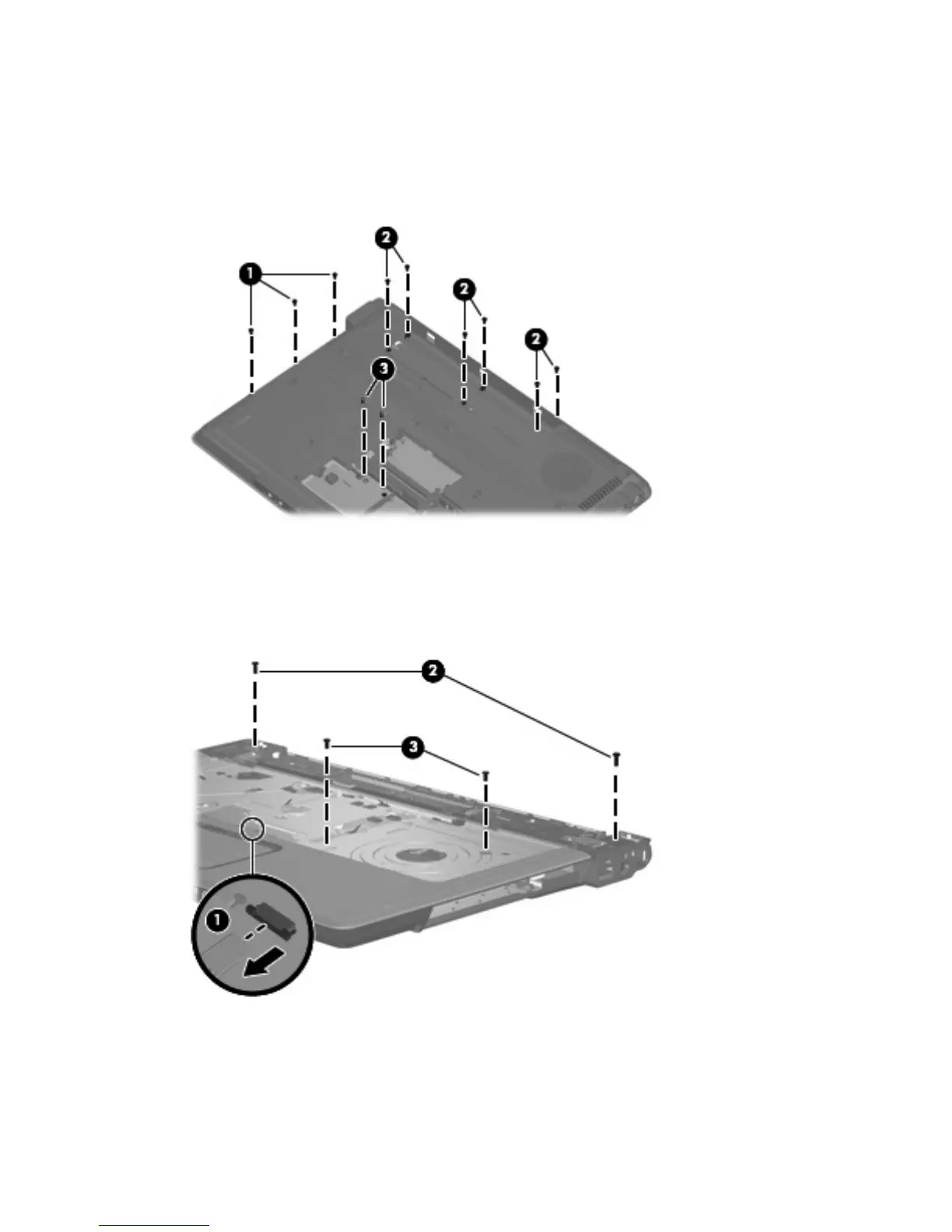
Remove the following:
(1) Three Phillips PM2.5×4.0 screws in the optical drive bay
(2) Six Phillips PM2.5×5.0 screws in the battery bay
(3) Two Hex HM5.0×9.0 standoffs in the memory/WLAN module compartment
4.
Turn the computer right-side up, with the front toward you.
5. Disconnect the TouchPad cable (1) from the system board.
6. Remove the two Phillips PM2.5×8.0 screws (2) and the two Phillips PM2.5×5.0 screws (3) that
secure the top cover to the computer.
64 Chapter 4 Removal and replacement procedures
 Loading...