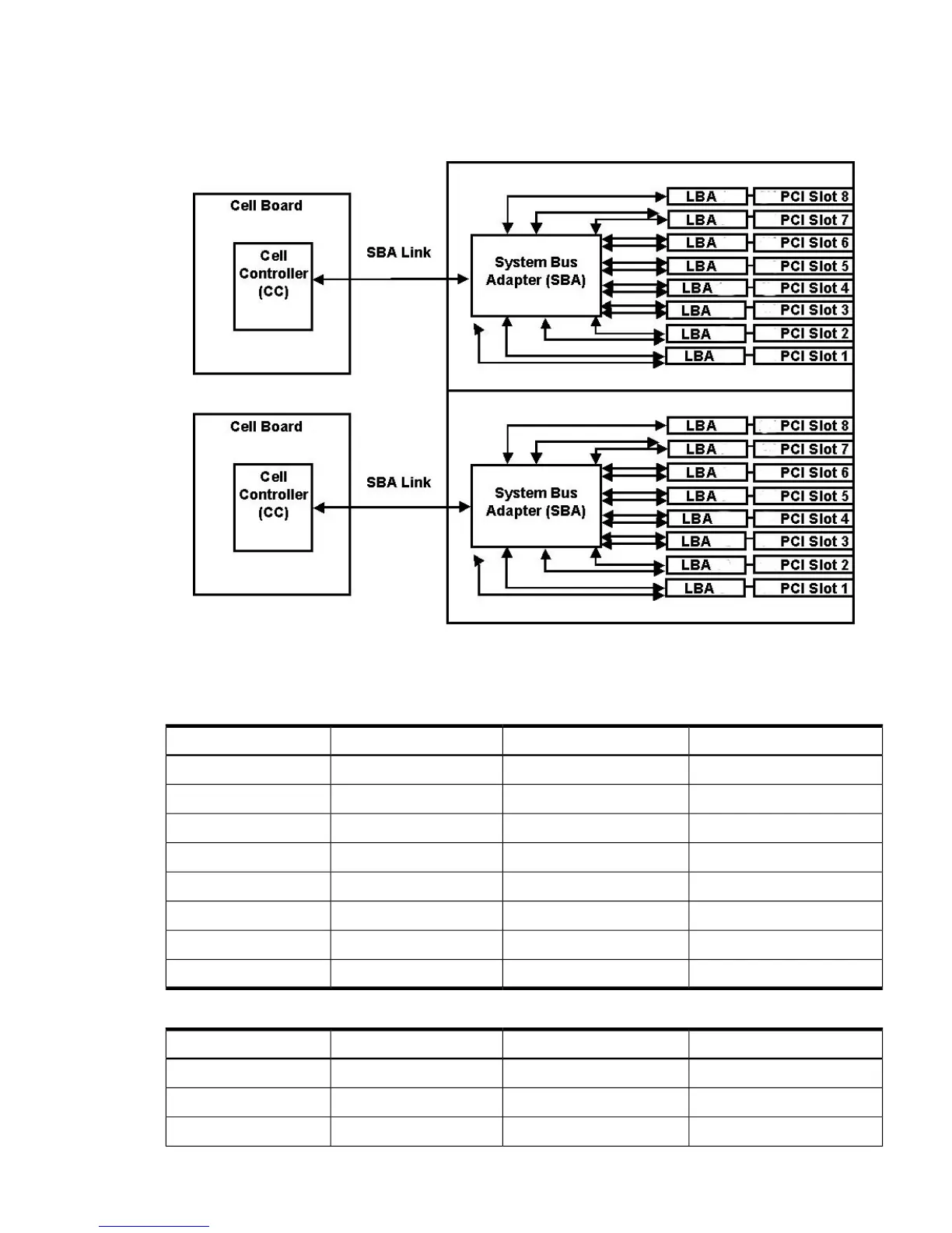
and at 266 MT/s for PCI-X mode 2 cards installed in mode 2 capable slots. When cell board 2 and
cell board 3 are present, the cell boards attach to their own associated SBA and LBA chips on the
PCI-X board in the Server Expansion Unit.
Figure 1-12 PCI-X Board to Cell Board Block Diagram
Table 1-6 and Table 1-7 list the mapping of PCI-X slots to boot paths. The cell column refers to
the cell boards installed in the server.
Table 1-6 PCI-X Slot Boot Paths Cell 0
PathRopesPCI SlotCell
0/0/8/1/08/910
0/0/10/1/010/1120
0/0/12/1/012/1330
0/0/14/1/014/1540
0/0/6/1/06/750
0/0/4/1/04/560
0/0/2/1/02/370
0/0/1/1/0180
Table 1-7 PCI-X Slot Boot Paths Cell 1
PathRopesPCI SlotCell
1/0/8/1/08/911
1/0/10/1/010/1121
1/0/12/1/012/1331
Detailed Server Description 25