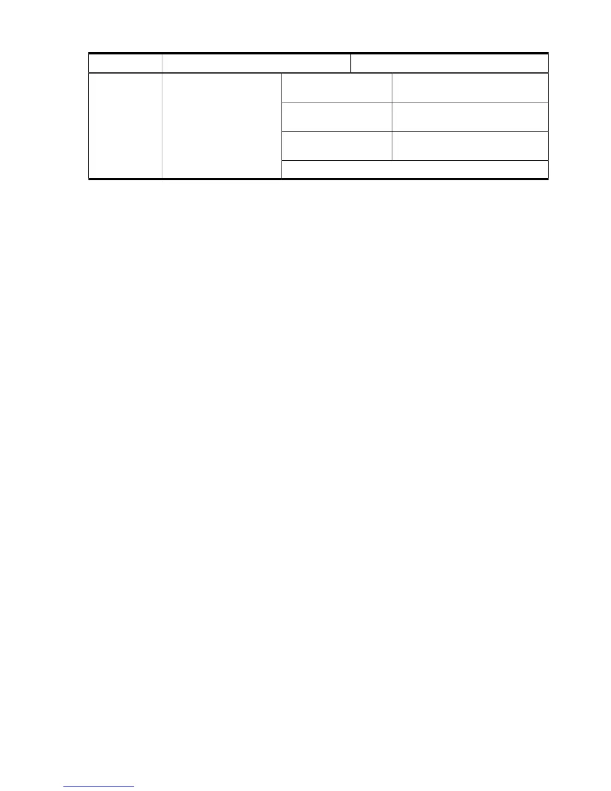
Table 2-9 Example ASHRAE Thermal Report (continued)
Condition
1 cell board, 2 CPUs, 2 GB, 1 core I/O
card
Minimum configurationASHRAE class
4 cell boards, 16 CPUs, 128 GB, 2 core
I/O cards, 16 I/O cards, 4 hard disks
Full configuration
2 cell boards, 8 CPUs, 64 GB, 1 core I/O
card, 8 I/O cards, 2 hard disks
Typical configuration
Environmental Temperature Sensor
To ensure that the system is operating within the published limits, the ambient operating
temperature is measured using a sensor placed on the server backplane. Data from the sensor is
used to control the fan speed and to initiate system overtemp shutdown.
Non-Operating Environment
The system is designed to withstand ambient temperatures between -40° C to 70° C under
non-operating conditions.
Cooling
Internal Chassis Cooling
The cabinet incorporates front-to-back airflow across the system backplane. Nine 120-mm fans
mounted externally on the front chassis wall behind the cosmetic front bezel push air into the
unit. Twelve 120-mm fans housed in cosmetic plastic fan carriers and mounted externally to the
rear chassis wall pull air through the unit.
Each fan is controlled by a smart fan control board embedded in the fan module plastic housing.
The smart fan control board receives fan control input from the system fan controller on the
system backplane and returns fan status information to the system fan controller. The smart fan
control board also controls the power and the pulse width modulated control signal to the fan
and monitors the speed indicator back from the fan. The fan status LED is driven by the smart
fan control board.
Bulk Power Supply Cooling
Cooling for the bulk power supplies (BPS) is provided by two 60-mm fans contained within each
BPS. Air flows into the front of the BPS and is exhausted out of the top of the power supply
though upward facing vents near the rear of the supply. The air is then ducted out of the rear of
the chassis.
PCI/Mass Storage Section Cooling
Six 92-mm fans located between the mass storage devices and the PCI card cage provide airflow
through these devices. The PCI fans are powered off of housekeeping power and run at full
speed at all times. The air is pulled through the mass storage devices and pushed through the
PCI card cage. Separation is provided between the PCI bulkheads to allow adequate exhaust
ventilation and to help reduce the localized airflow dead spots that typically occur at the faceplate
tail of each PCI card.
Standby Cooling
Several components within the chassis consume significant amounts of power while the system
is in standby mode. The system fans will run at a portion of full speed during standby to remove
38 System Specifications