2-31
Installing the Switch
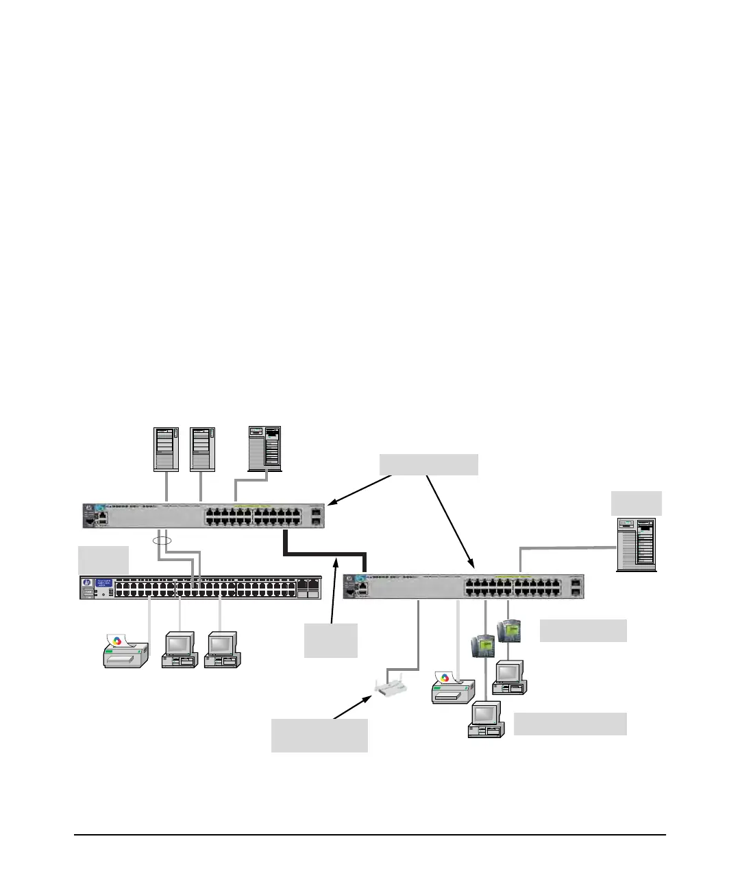
Sample Network Topologies
In the illustration above, two “Fast” Ethernet hubs with PCs, printers, and local
servers attached, are both connected to a Switch. The devices attached to the
two hubs can now communicate with each other through the switch. They can
also all communicate with the server that is connected to a 1000Base-T port
on the switch.
Because the Switch has the “IEEE Auto MDI/MDI-X” features, the connections
between the switch and the hubs, and between the switch and end nodes or
servers can be through category 5 straight-through or crossover twisted-pair
cable.
Category 3 or 4 cable can also be used if the connection is 10 Mbps only. In all
cases, the device ports must be configured to auto negotiate the link
characteristics for this feature to work.
The switch, in turn, can be connected to a network backbone through fiber-
optic cabling connected to a Gigabit-SX, -LX, or -LH transceiver installed in
the switch. Now, all the devices on these network segments can access other
network resources that are connected elsewhere on the network backbone.
Figure 2-26. Example as a Segment Switch Implementing PoE/PoE+
Server
PCs and peripherals
IP Telephones
Stacking
cables
Wireless Access
Point
Non-PoE
Switch
E3800-24G Switch
 Loading...