3. Feed the FFCs, the wire connectors, and the ground strap through the opening in the scanner-
assembly base.
CAUTION: Examine how the FFCs and wire-harnesses are routed before moving them.
Do not bend or fold the FFCs during the removal or reinstallation process.
Figure 6-35 Removing the scanner assembly top cover (2 of 4)
Reinstallation tip When reinstalling the FFCs, make sure that the ferrites snap into the clips in
the base.
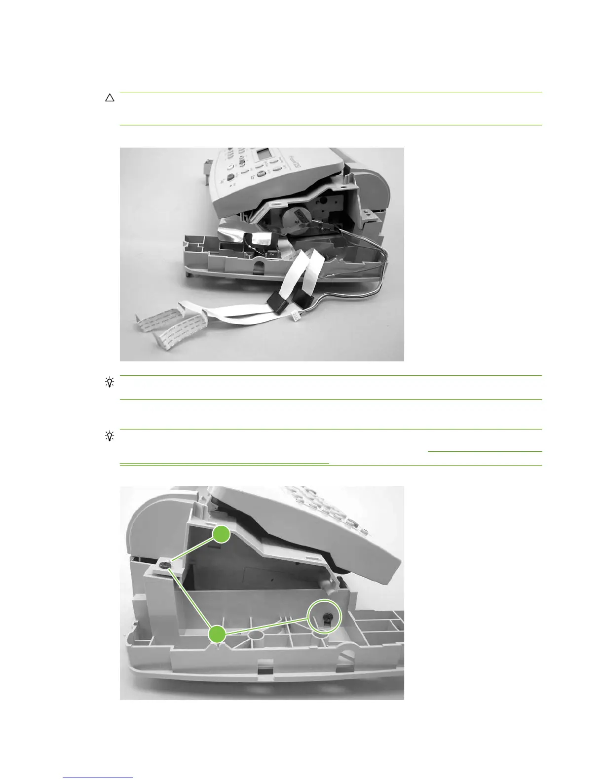
4. Remove the two left-side mounting screws (callout 2).
Reinstallation tip When reinstalling the scanner assembly top cover, make sure that it is seated
on the alignment pins. The plastic pin (callout 3) is behind the screw in
Figure 6-36 Removing the
scanner assembly top cover (3 of 4) on page 94.
Figure 6-36 Removing the scanner assembly top cover (3 of 4)
2
3
94 Chapter 6 Removal and replacement ENWW