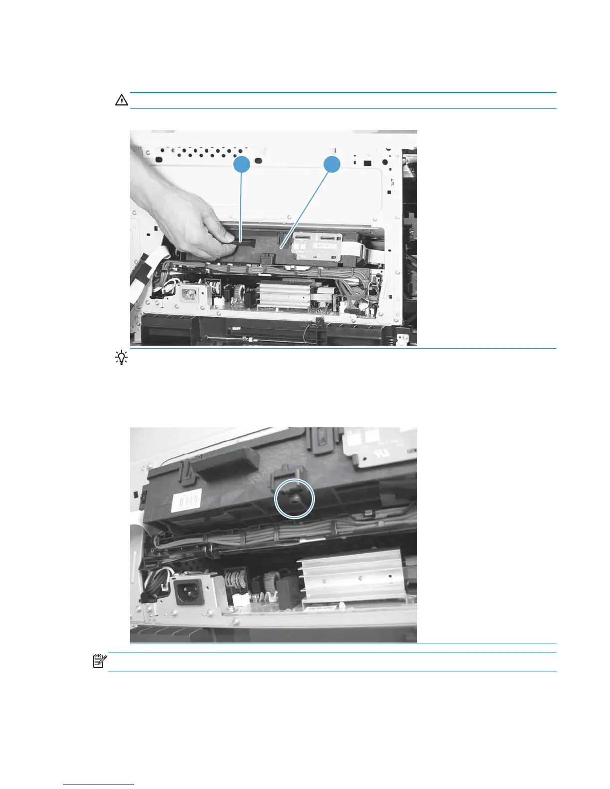
6. While holding up the handle (callout 1), pull the laser/scanner (callout 2) up slightly and then out of the
product.
CAUTION: Do not touch the protective glass strip on top of the assembly.
Figure 2-57 Remove the laser/scanner assembly (4 of 4)
1 2
Reinstallation tip Align the assembly with the guides on the left side of the opening when reinstalling
the assembly.
Align the pin on the bottom of the assembly with the hole in the product when reinstalling the
assembly. After pushing the assembly into the product, you might have to pull the assembly slightly
forward to seat the pin in the hole.
NOTE: Perform two full calibrations from the control panel after replacing the laser/scanner.
ENWW Removal and replacement procedures 127
 Loading...