2. Remove one screw (callout 1), and then remove the sheet-metal plate (callout 2).
Figure 2-86 Remove the main drive assembly (2 of 17)
1
2
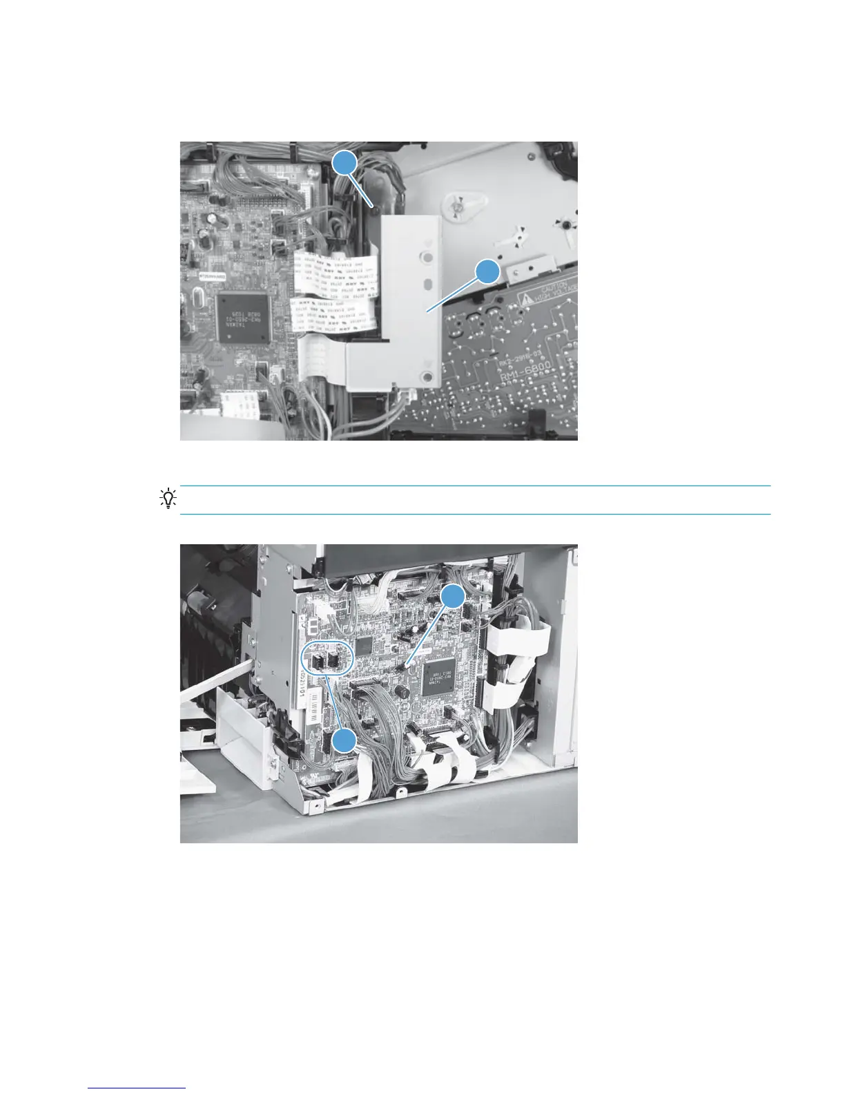
3. Disconnect twenty-two connectors and six FFCs on the DC controller PCA (callout 1).
TIP: Three connectors (callout 2) should be empty when the DC controller is reinstalled.
Figure 2-87 Remove the main drive assembly (3 of 17)
1
2
ENWW Removal and replacement procedures 151
 Loading...