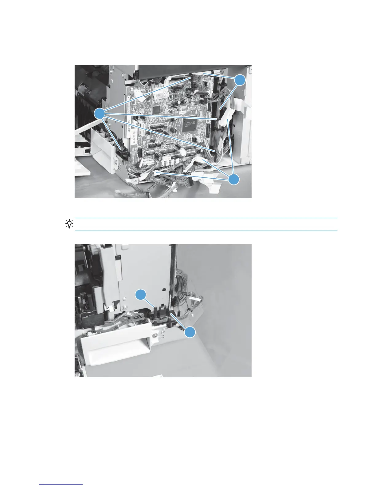
4. Disconnect three intermediate connectors (callout 1), and then release the wire harnesses (callout 3)
from the guides (callout 2).
Figure 2-88 Remove the main drive assembly (4 of 17)
1
3
2
5. Release one tab (callout 1), and then remove the guide (callout 2).
TIP: Release the wire harnesses from the guide as you remove it.
Figure 2-89 Remove the main drive assembly (5 of 17)
2
1
152 Chapter 2 Removal and replacement ENWW
 Loading...