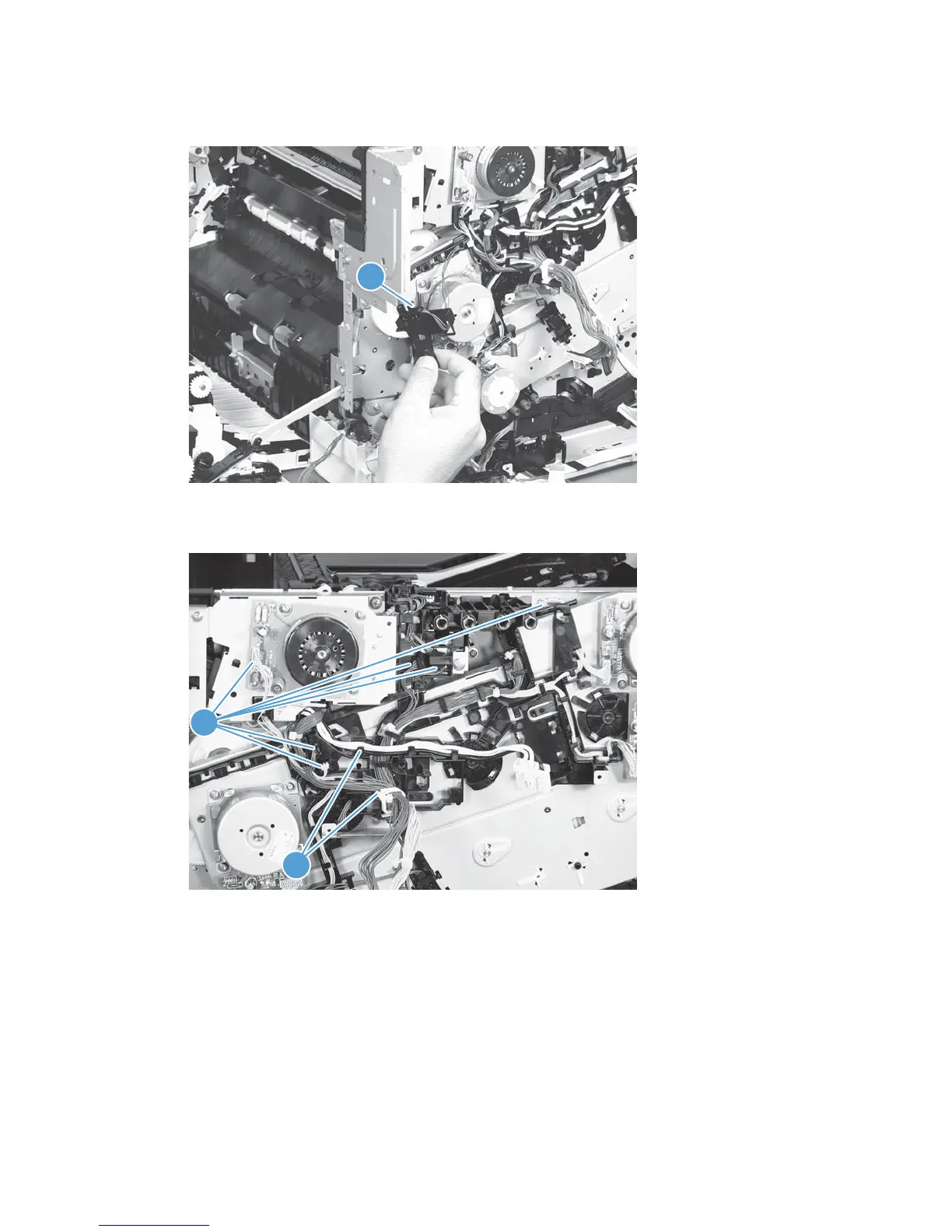
15. Disconnect one connector (callout 1), and then remove the sensor assembly.
Figure 2-99 Remove the main drive assembly (15 of 17)
1
16. Disconnect six connectors (callout 1), and then release the wire harnesses from the guides (callout 2).
Figure 2-100 Remove the main drive assembly (16 of 17)
1
2
158 Chapter 2 Removal and replacement ENWW
 Loading...