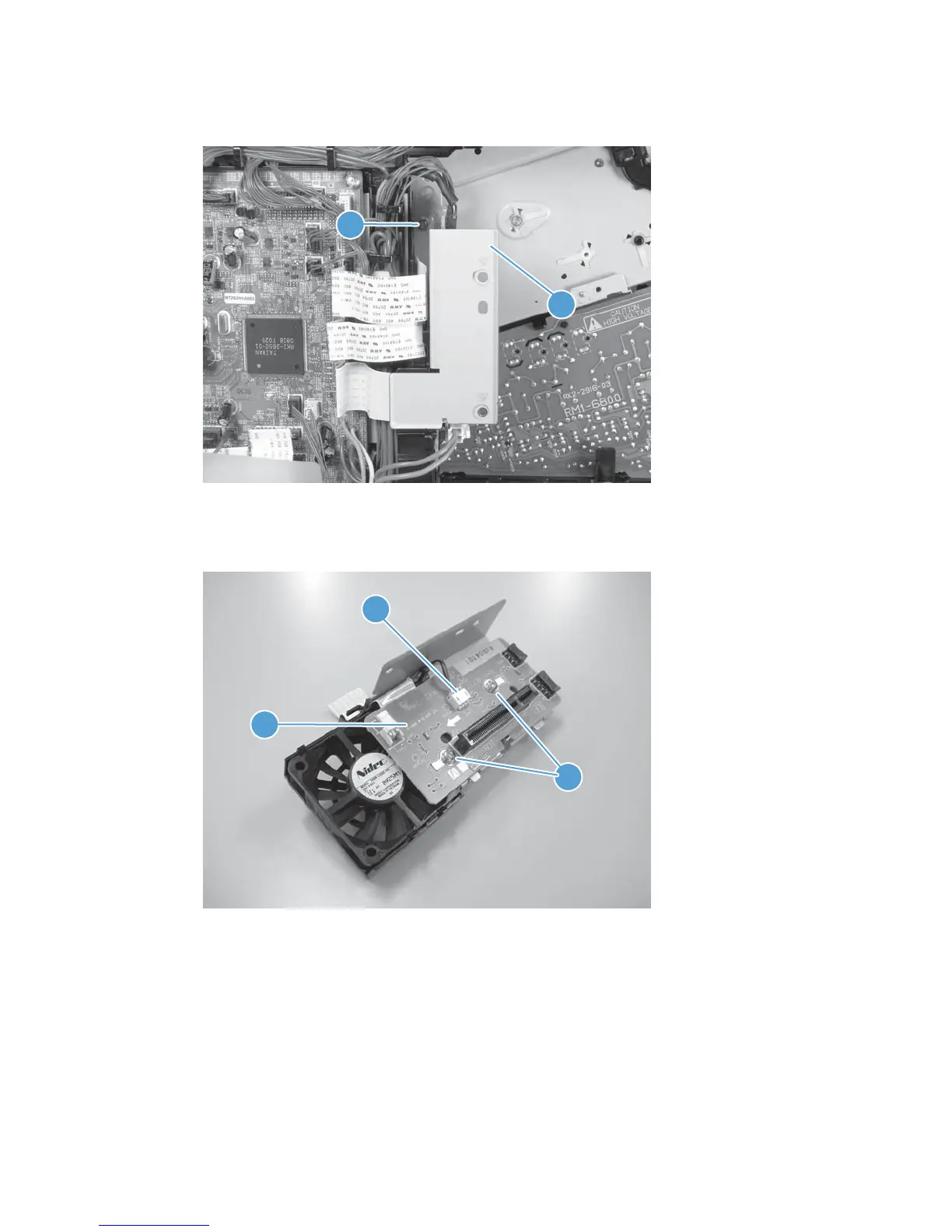
2. Remove one screw (callout 1) and then remove the sheet-metal plate (callout 2).
Figure 2-153 Remove the formatter fan (2 of 5)
2
1
3. Disconnect one connector (callout 1), remove two screws (callout 2), and then remove the inter connect
board (IBC) PCA (callout 3) from the assembly.
Figure 2-154 Remove the formatter fan (3 of 5)
2
1
3
ENWW Removal and replacement procedures 195
 Loading...