1
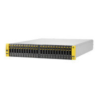
Unpack and inspect the array hardware.
Save the original packaging.
3
4
5
Hewlett Packard Enterprise Development LP. • 211 River Oaks Parkway, San Jose, CA 95134 • support@nimblestorage.com • +1.408.432.9600
2
Important!
• Before beginning, download and read the Release Notes, available at
https://infosight.hpe.com/. Type your email address and password, and
click Login. If you do not have a password, click New user? Enroll now.
• The CS Series power supplies are 220VAC or 110VAC autodetecting.
• This product is intended for installation in restricted-access locations only,
such as a dedicated equipment room or an electrical closet.
If you are installing more than one Nimble array, download and
read the Nimble Storage Installation Guide, available at
https://infosight.hpe.com/. (For CS235 models, see Array Quick
Start for CS235, CS300, CS500, CS700)
https://infosight.nimblestorage.com
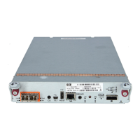
eth2
eth1 tg1 tg2
eth2
eth1
eth5
eth3
eth6
eth4
Controller with 1GBE Ethernet ports Controller with 10GbE Ethernet ports
Note: For 10BaseT, port tg1 is labeled eth3 and tg2 is labeled eth4.
What you need for each array
• 19-inch four-post square-hole rack
• 3U space available in the 19-inch rack
• Phillips screwdriver
• At least four CAT 6 Ethernet cables
• At least two 10GbE network switches are recommended.
• Two power outlets on separate circuits:
• Steady state: 5A @ 120V
ARRAY QUICK START GUIDE
CS200 and CS400 Series Hardware Installation
Important!
If you plan to add any Nimble
ES1-Series expansion shelves,
fully congure the array before
you connect any shelves to it.
6
Install the inner rails onto the array.
a. Align the holes in the inner rails with the hooks on the sides of
the chassis.
b. Slide the rails toward the front of the chassis to seat the hooks.
c. Install the set screws to secure the inner rails in position.
d. Repeat steps a, b and c on the other side.
Separate the inner rails from the rail assemblies.
a. Press the catch at the front end of the middle rail.
b. Slide the inner rail out of the rail assembly.
c. Repeat steps a and b on the other side.
Inner rail
Middle rail
Slide rails apart
Press here
Install the rail assemblies into the rack.
Important!
If the rack has round holes, install the provided square-hole adapter
as shown at right.
.
Note that cabinet rack holes are not evenly spaced. To ensure that
the thumbscrews align correctly, align the rack at the border of a unit.
The middle rails attach to the front posts. The outer rails attach to the
back posts.
a. Align the upper hook of the rail at the position you want.
b. Press the rail into the post and slide it down to lock it in position.
c. Repeat steps a and b on the other side. (See diagram 4c.)
Slide the array into the rack.
a. Insert the chassis into the rack, back side rst.
b. Gently slide the chassis into position.
When you hear a click, the inner rails have locked into the rail
assembly.
CAUTION!
The chassis weighs over 34 kg (76 lb). Always use two people or
a server lift when lifting the chassis.
OPEN
OPEN
OPEN
OPEN
OPEN
OPEN
OPEN
OPEN
OPEN
OPEN
OPEN
OPEN
OPEN
OPEN
OPEN
OPEN
Model: CS200 , CS4 00, E S1
100-140 Vac, 60-50 Hz, 11.5-8 A
180-240 Vac, 60-50 Hz, 8-5. 5A
Assembled in the USA
I.T.E
E340293
!
!
Inner rail – Right
Set screw
Inner rail – Left
Set screw
Nimble Array
chassis
rail
Cable the array.
Important!
For failover to operate correctly, cable the same port on each controller into the SAME switch and subnet. Ensure that:
• Both controllers are connected to the network.
• iSCSI initiators have a network path to both controllers.
Connect one member of each interface pair to the same switch. If your switches have multiple subnets congured, make sure that each
interface pair is connected to switch ports on the same subnet.
See the “Install the Nimble Array” chapter in the Nimble Storage Installation Guide.
CAUTION!
Start-up current draw may exceed 6A.
3
Middle rail (right)
Outer rail (right)
Front post Back post
Top hook goes into bottom hole
Tabs point upward
1
2
3
Square holes to the inside
Top view of rack
(Rail assemblies correctly installed in a rack.)
7
Apply power.
Plug one power cord from each controller into a separate circuit and apply power. If the power
does not come on automatically, press the power button ( ) on the front of the array.
Secure the array chassis to the rack.
The chassis has two handles. Each handle has a screw that secures
the chassis so it does not slide out of the rack.
Tighten the screw in each handle.
8
1
6
• Start-up: 6A @ 120V
2
4
5
4c