EasyManua.ls Logo

HP P4819 User Manual

HP P4819
87 pages
To Next Page IconTo Next Page
Page #1 background imageLoading...
Page #1 background image
CHASSIS
SERVICE MANUAL
SPECIFICATIONS
P4819
CR1
US Model
Canadian Model
AEP Model
S. Hemisphere Model
Japan Model
Chinese Model
Chassis No. SCC-L33S-A
21-inch Color Monitor
HP
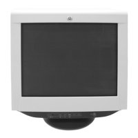
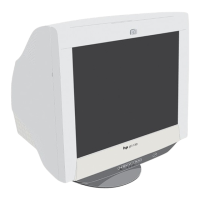
CRT 0.24 mm aperture grille pitch
21 inches measured diagonally
90-degree deflection
FD Trinitron
Viewable image size Approx. 403.8 × 302.2 mm (w/h)
(16 × 12 inches)
19.8" viewing image
Resolution
Recommended Horizontal: 1600 dots
Vertical: 1200 lines
Input signal levels Video signal
Analog RGB: 0.700 Vp-p
(positive), 75
SYNC signal
H/V separate or composite sync:
TTL 2 k, Polarity free
Sync on Green: 0.3 Vp-p
(negative)
Standard image area Approx. 388 × 291 mm (w/h)
(15
3
/8 × 11
1
/2 inches)
or
Approx. 364 × 291 mm (w/h)
(14
3
/8 × 11
1
/2 inches)
Deflection frequency* Horizontal: 30 to 130 kHz
Vertical: 48 to 170 Hz
AC input voltage/current 100 to 240 V, 50 – 60 Hz, 2.0 – 1.0 A
Power consumption Approx. 145 W
Dimensions Approx. 497 × 502 × 490.3 mm (w/h/d)
Mass Approx. 30.5 kg
Plug and Play DDC2B/DDC2Bi, GTF**
* Recommended horizontal and vertical timing condition
Horizontal sync width duty should be more than 4.8% of
total horizontal time or 0.8 µs, whichever is larger.
Horizontal blanking width should be more than 2.3 µsec.
Vertical blanking width should be more than 450 µsec.
** If the input signal is Generalized Timing Formula (GTF)
compliant, the GTF feature of the monitor will automatically
provide an optimal image for the screen.
Design and specifications are subject to change without notice.
Question and Answer IconNeed help?

Do you have a question about the HP P4819 and is the answer not in the manual?

HP P4819 Specifications

General IconGeneral
BrandHP
ModelP4819
CategoryMonitor
LanguageEnglish

Summary

DISASSEMBLY

Cabinet Removal

Procedure for removing the monitor's outer cabinet.

A1 Board (C Block) Removal

Steps to remove the A1 board (C BLOCK) assembly.

A1 Board Removal

Detailed steps for removing the A1 board.

Bezel Assembly and H7 Board Removal

Procedure for removing the bezel assembly and H7 board.

D Board Removal

Instructions for removing the D board.

Picture Tube Removal

Steps for safely removing the CRT picture tube and anode cap.

SAFETY RELATED ADJUSTMENT

HV ADJ

High Voltage adjustment procedure.

HV Regulator Circuit Check

Check and adjustment for the HV regulator circuit.

HV Protector Circuit Check

Procedure to check the HV protector circuit.

Beam Current Protector Circuit Check

Check for the beam current protector circuit.

ADJUSTMENTS

Landing Rough Adjustment

Initial adjustment for landing.

Landing Fine Adjustment

Detailed fine-tuning for landing adjustment.

ELECTRICAL PARTS LIST

Related product manuals