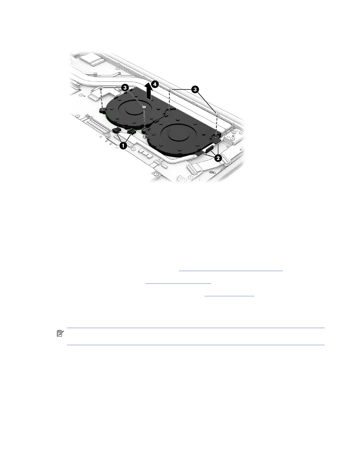
4. Remove the fan (4) from the computer.
To replace the fan, reverse the removal procedures.
Display assembly
To remove and disassemble the display assembly, use these procedures and illustrations.
The display assembly is available only at the the subcomponent level. Subcomponent level spare part
information is available in the subcomponent level disassembly subsection.
Before removing the display assembly, follow these steps:
1. Prepare the computer for disassembly (see Preparation for disassembly on page 33).
2. Remove the bottom cover (see Bottom cover on page 33).
3. Disconnect the battery cable from the computer (see Battery on page 35).
Remove the display assembly:
1. Remove the WLAN antenna plate (1) that secures the WLAN antenna cables to the WLAN module.
NOTE: The WLAN antenna plate is available in the Miscellaneous Kit, spare part number
N94803-001.
2. Carefully disconnect the two WLAN antenna cables (2) from the terminals on the WLAN module.
Computer models have either one or two WLAN antennas. On models with two antennas, the #1
WLAN antenna cable connects to the WLAN module #1 Main terminal. The #2 WLAN antenna cable
connects to the WLAN module #2 Aux terminal.
44
Chapter 5 Removal and replacement procedures for authorized service provider parts