6.
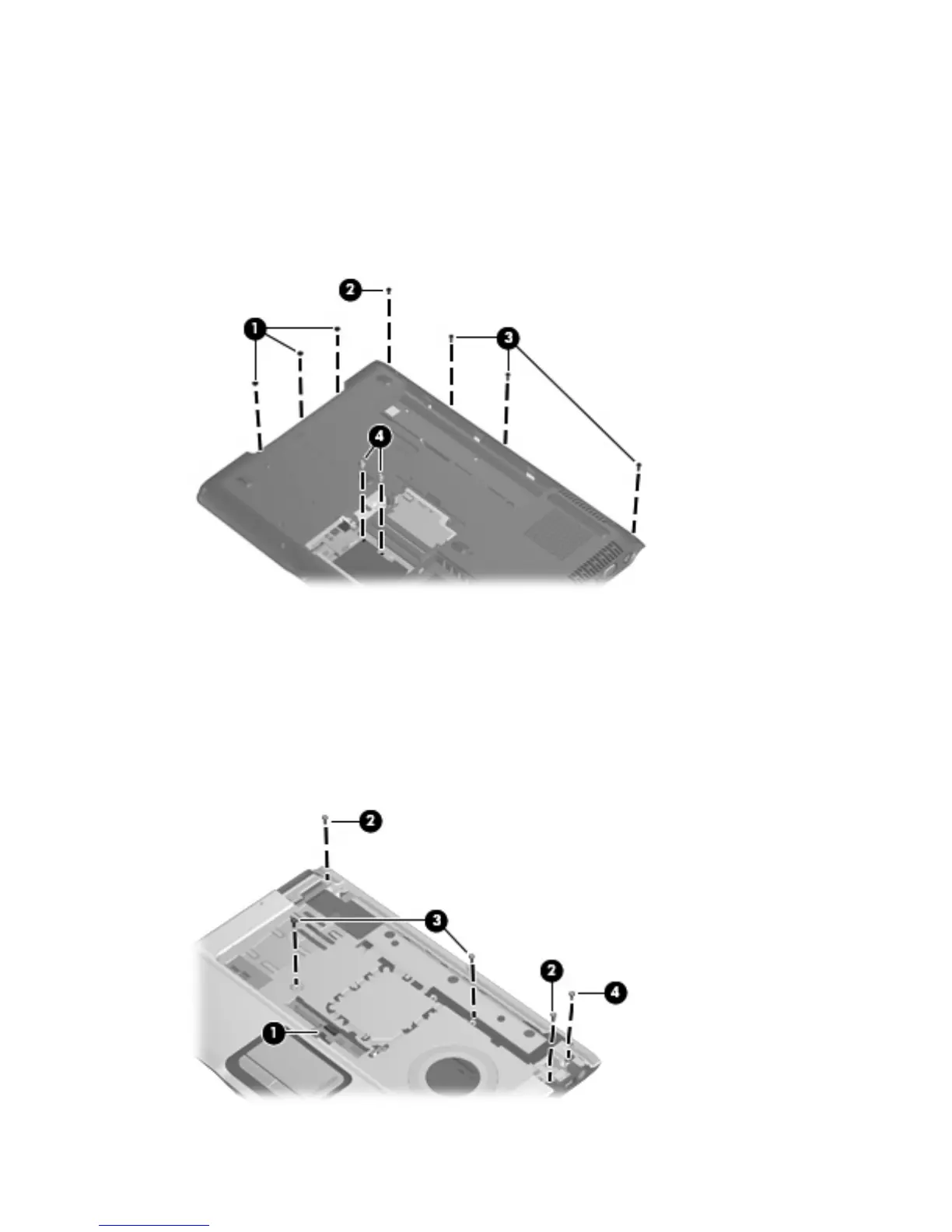
Remove the following:
(1) Three Phillips PM2.5×2.0 screws in the optical drive bay
(2) One Phillips PM2.5×5.0 screw on the rear edge of the base enclosure
(3) Three Phillips PM2.5×7.0 screws on the rear edge of the base enclosure that secure the top cover
trim to the computer
(4) Two HM5.0×9.0 standoffs in the memory/WLAN module compartment
7.
Turn the computer right-side up, with the front toward you.
8. Release and disconnect the TouchPad cable (1) from the ZIF connector on the system board.
9.
Remove the following screws:
(2) Two Phillips PM2.5×7.0 screws
(3) Two Phillips PM2.5×4.0 screws
(4) One Phillips PM2.5×5.0 screw that secures the top cover trim to the computer
76 Chapter 4 Removal and replacement procedures

 Loading...