10. Remove the display assembly (see Display assembly on computers with 15.6-in displays
on page 74).
11. Remove the palm rest (see
Palm rest on page 69).
12. Remove the hard drive (see
Hard drive on page 72).
13. Remove the top cover (see
Top cover on page 81).
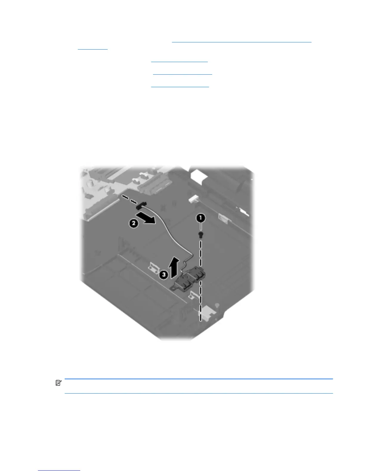
Remove the USB connector assembly:
1. Position the computer right-side up with the right side toward you.
2. Remove the Phillips PM2.5×3.0 screw (1) that secures the USB connector assembly to the base
enclosure.
3. Disconnect the cable from the system board (2).
4. Remove the USB connector assembly (3) from the base enclosure.
Reverse this procedure to install the USB connector assembly.
RJ-11 connector assembly
NOTE: The RJ-11 connector assembly is included in the Base Cable Kit, spare part number
613224-001 for 15.6-in computers.
Component replacement procedures 95
 Loading...