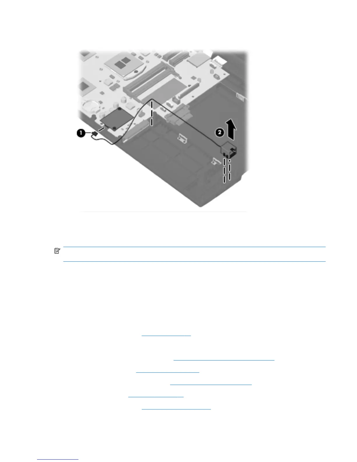
3. Lift the RJ-11 connector (2) from its holder and out of the base enclosure.
Reverse this procedure to install the RJ-11 connector assembly.
Power connector assembly
NOTE: DThe power connector assembly is included in the Base Cable Kit, spare part number
613224-001 for computers wit 15.6-in displays.
Before removing the power connector assembly, follow these steps:
1. Shut down the computer. If you are unsure whether the computer is off or in Hibernation, turn
the computer on, and then shut it down through the operating system.
2. Disconnect all external devices connected to the computer.
3. Disconnect the power from the computer by first unplugging the power cord from the AC outlet
and then unplugging the AC adapter from the computer.
4. Remove the battery (see
Battery on page 48).
5. Remove the following components:
a. Switch cover and keyboard (see
Switch cover and keyboard on page 49)
b. Optical drive (see
Optical drive on page 54)
c. Power button board cable (see
Power button board on page 56)
d. Speakers (see
Speakers on page 58)
e. Thermal shield (see
Thermal shield on page 59)
Component replacement procedures 97
 Loading...