Do you have a question about the HP ProLiant DL160 - G5 Server and is the answer not in the manual?
Explains the warranty service providing replacement parts free of charge.
Lists and illustrates the mechanical spare parts for the server.
Details system components and spare parts for non-hot-plug HDD configurations.
Details system components and spare parts for hot-plug HDD configurations.
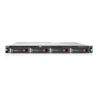
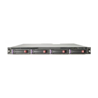
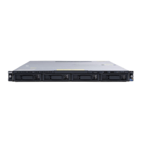
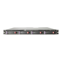
Identifies and describes components on the server's front panel.
Identifies and describes components on the server's rear panel.
Identifies and describes components located on the server's system board.
Describes the LED indicators found on the server's front panel.
Explains the status indicated by the server's power LED.
Details the LED indicators for hard drive activity and status.
Describes the LED indicators located on the server's rear panel.
Describes the LED indicator present on the server's system board.
Provides precautions to prevent damage from electrostatic discharge (ESD).
Outlines the necessary steps before installing or removing server components.
Highlights important warnings and cautions before server installation.
Explains symbols indicating potentially hazardous conditions on equipment.
Provides instructions on how to completely power down the server.
Describes the removal and replacement of the server's system covers.
Provides guidelines for proper cable management within the server.
Details power supply and system board cable connections.
Describes the server's drive bay configurations for HDDs and optical drives.
Explains the installation and removal of hard drives.
Details processor installation, removal, and thermal considerations.
Covers memory module installation, removal, and supported configurations.
Explains system board PCI expansion slots and riser card installation.
Provides instructions for replacing the system battery.
Details the procedure for removing the system board from the chassis.
Details the procedure for installing a new system board.
Provides steps to remove the server's power supply unit.
Provides steps to install a new power supply unit.
Details the procedure for removing a system fan.
Details the procedure for installing a new system fan.
Covers BIOS software, setup utility, accessing, navigating, and menu bar.
Details Advanced, IPMI, Boot, Security, and Exit menus in BIOS.
Provides steps for BIOS update and clearing CMOS.
Covers POST, error messages, and troubleshooting procedures.
Lists the physical and hardware specifications of the server.
| Processor Socket | LGA 771 |
|---|---|
| Memory Slots | 8 DIMM slots |
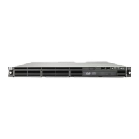
| Form Factor | 1U rackmount |
| Processor | Intel Xeon 5400 series (quad-core) |
| Chipset | Intel 5000P |
| Memory | Up to 32GB DDR2 |
| Storage | Up to 4 x 3.5" SAS/SATA hard drives |
| RAID Support | HP Smart Array P400 controller (optional) |
| Network | Embedded NC373i Multifunction Gigabit Network Adapter with TCP/IP Offload Engine |
| Operating System Support | Microsoft Windows Server, Red Hat Enterprise Linux, SUSE Linux Enterprise Server |
| Management | Integrated Lights-Out 2 (iLO 2) standard |