Item Description
4 GbE LAN port for NIC 2
5 Mgmt port (optional)
6 Low-profile PCI expansion card slot cover
7 Rear Hard Drives
8 UID LED/switch
9 GbE LAN port for NIC 1
10 Rear Panel USB 2.0 port 2/3
11 VGA port
12 Power supply 1 cable socket
Figure 6 Rear Panel Components for DVD-ROM PCI Cage
Item Description
1 Power supply 2 cable socket
2 Serial port
3 T-10/T-15 wrench
4 GbE LAN port for NIC 2
5 Mgmt port (optional)
6 Optical Disc Drive
7 Full-height/full-length PCI expansion card slot covers
8 UID LED/switch
9 GbE LAN port for NIC 1
10 Rear Panel USB 2.0 port 2/3
11 VGA port
12 Power supply 1 cable socket
CAUTION: For more detailed information relating to
installation of options, refer to any installation instructions
that came with the option, as well as the HP ProLiant
DL180 G6 Server Maintenance and Service Guide.
System board components
Figure 7 System Board Components
Item Description
1 PCIe slot
2 Mgmt card connector
3 PCIe slot
4 DIMM slot 6C for processor 2
5 DIMM slot 1D for processor 2
6 Processor 2
7 Processor 1
8 DIMM slot 6C for processor 1
9 4-pin power connector
10 System power connector
11 DIMM slot 1D for processor 1
12 Fan connector 1/2
13 8-pin power connector
14 Fan connector 3/4 (Fan 4 is unused)
15 Internal USB 2.0 port 4
16 Backplane I
2
C connector
17 Fan connector 5/6 (Fan 6 is unused)
18 Backplane SGPIO connector
19 Power supply EFF connector
20 Internal USB 2.0 port 5
21 3 V CMOS battery (CR2032)
22 Backplane power connector
23 LCD connector (optional)
24 Front panel USB 2.0 port 0/1
25 Front panel header
26 TPM connector
27 System maintenance jumper
28 SATA connector
29 PCIe slot
Server configuration resources
In addition to this Installation Sheet, other resources are available for
more information regarding the configuration and maintenance of
your server:
• For safety information and detailed procedures relating to
installation of options, refer to any installation instructions that
came with the option, as well as the HP ProLiant DL180 G6
Server Maintenance and Service Guide.
• For safety information and detailed procedures related to the
rest of the steps listed in the “Configuring the Server” section,
refer to the relevant chapter of the HP ProLiant DL100 Series
Server User Guide.
• For information relating to system BIOS configuration and
operating system installation, refer to the relevant section of the
HP ProLiant DL180 G6 Server Software Configuration Guide.
• Refer to the HP ProLiant DL180 G6 Server Easy Set-up CD for
additional information and updates not provided in this
installation sheet. You can also access additional information
and documentation from the HP website at
http://www.hp.com/
, either by connecting directly or through
the Easy Set-up CD.
Server configuration overview
The steps listed below give an overview of the necessary setup
procedures for preparing the HP ProLiant DL180 Generation 6
Server for operation:
1. Connect the AC power cord and peripheral devices.
2. Power on the server.
3. Press “F10” to enter BIOS setup.
4. Note the server BIOS version.
5. Verify the server BIOS version against the latest BIOS version
listed for this server.
6. If you do not have the latest BIOS, update the BIOS now. Refer
to the HP ProLiant DL180 G6 Server Maintenance and Service
Guide.
7. Install a supported operating system of your choice. For
detailed procedures, refer to the documentation provided by
the operating system vendor.
Pre- and post-installation
procedures
When installing additional options in your HP ProLiant DL180 G6
Server, observe the following procedures:
Pre-installation procedures
1. Turn off the server and all the peripherals connected to it.
2. Disconnect the AC power cord from the power supply cable
socket located on the server rear panel to reduce the risk of
electrical shock.
3. If the server is installed in a rack, remove the server and place
it on a flat surface.
4. Remove the top cover by following the procedure described
later in the “Opening the server” section.
Post-installation procedures
1. Be sure all components are installed according to the described
step-by-step instructions.
2. Check to make sure you have not left loose tools or parts inside
the server.
3. Reinstall the PCI cage, air baffle, peripherals, and system
cables that you have removed.
4. Reinstall the top cover.
5. Reinstall the server into the rack.
6. Connect all external cables and the AC power cord to the
system.
7. Press the power button on the front panel to turn on the server.
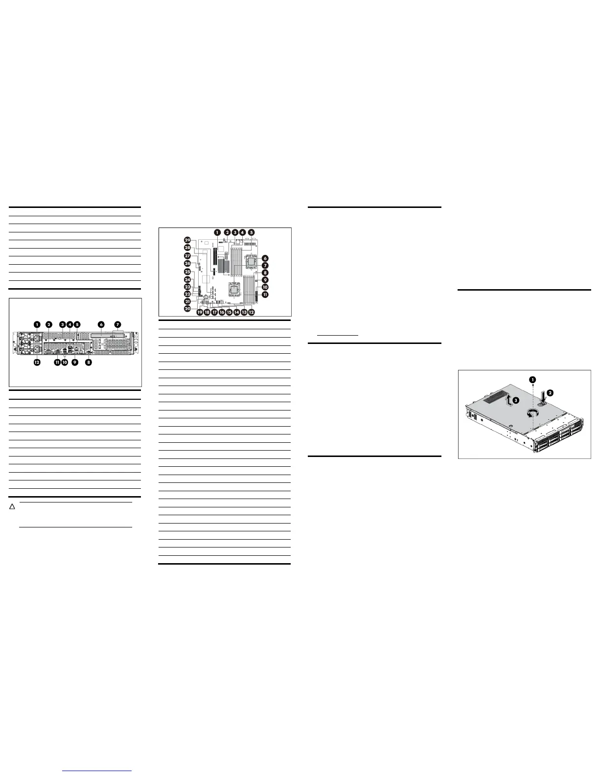
Opening the server
The top cover is removable. You need to remove the top cover
before you can remove or replace a server component.
To remove the top cover:
1. Loosen the screw on the top cover with a T-10 wrench.
2. Press the latch on the top cover.
3. Slide the cover toward the rear of the server and then lift the
top cover to remove it from the chassis. Lift the top cover away
from the chassis.
Figure 8 Removing the Top Cover
 Loading...