Installing a hard drive
The drive bays on the front panel can accommodate up to twelve
3.5 in. hard drives. You can install either SAS hard drives or SATA
hard drives in the server.
CAUTION: Drives can be damaged by static electricity.
Before handling drives, touch an unpainted metal surface
to discharge static electricity.
To install the hard drive:
1. Push the hard drive assembly into the drive bay until it stops.
2. Press the hard drive carrier latch inward until it clicks.
Figure 9 Installing the Hard Drive
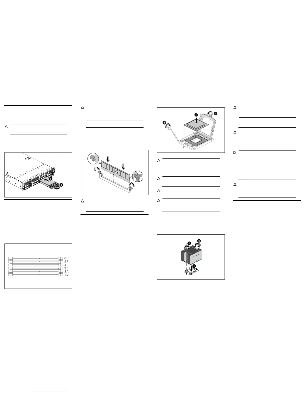
Installing a memory module
• Installation guide for 1P configuration:
o Follow the sequence of 2A, 4B, 6C, 1D, 3E, and 5F for the
corresponding processor when installing the memory.
• Installation guide for 2P configuration:
o Follow the sequence of 2A, 4B, 6C, 1D, 3E, and 5F for the
corresponding processor when installing the memory.
o Install at least one memory DIMM for each processor.
o The memory quantity installed for each processor can be
different.
Figure 10 DIMM Population
CAUTION: DIMMs can be damaged by improper
handling. Always use an anti-static wrist strap and
grounding mat, and discharge static electricity before
touching DIMMs.
NOTE: Refer to “System board components” in this
document for the DIMM locations.
To install the memory module:
1. Align the notch on the bottom edge of the memory module with
the keyed surface of the DIMM slot and then fully press the
memory module into the slot until the holding clips snap back in
place.
Figure 11 Installing the Memory Module
CAUTION: DIMM slots are structured to ensure proper
installation. If you insert a DIMM but it does not fit easily
into the slot, you may have inserted it incorrectly. Reverse
the orientation of the DIMM and insert it again.
Installing a processor
To install the processor:
1. Insert the processor into the socket, using the keys on the
processor.
2. Engage the retention plate and the load lever.
Figure 12 Installing the Processor
For processor removal, reverse the above installation procedures.
CAUTION: With the load lever and the retention plate
disengaged, hold the processor by its edges and align it
over the empty processor socket. Make sure that you
properly align the processor with the orientation notch on
the socket.
CAUTION: To prevent overheating or a possible system
crash, use only a heat sink model specified for the HP
ProLiant DL180 G6 Server.
CAUTION: Align pin 1 on the processor with pin 1 on the
processor socket, or pin damage will occur.
CAUTION: HP recommends using Shin-Etsu X-23-7783D
thermal grease compound for your ProLiant server. Apply
the grease to the top of the processor in either a “5-Dot”
or “S” shaped pattern. Ensure even distribution.
To install the heat sink:
1. Properly align the heat sink spring-loaded screws to the system
board mounting holes.
2. Tighten the spring-loaded screws clockwise to secure the heat
sink connection to the system board.
Figure 13 Installing the Heat Sink Assembly
CAUTION: Be sure that the heat sink sits squarely on the
processor, or overheating and damage to the processor
may occur.
NOTE: When installing two heat sinks, it is recommended
to put the heat sinks with the 14-fin side facing the
DIMMs.
CAUTION: Do not over-tighten the spring-loaded screws
to prevent them from breaking off. A maximum torque of
6 inch-lb is set for each screw. Rotate the heat sink a few
degrees to the left and right to break the bonding of the
thermal grease before removing the heat sink from the
processor.
IMPORTANT: If the heat sink has been removed for any
reason, it is critical that you apply more thermal interface
material to the integrated heat spreader on the processor
to ensure proper thermal bonding between the processor
and the heat sink. Clean the contact surface of both the
processor and heat sink with an alcohol pad, then re-
apply an HP-approved thermal interface material before
reinstalling the processor. Use a pattern of five dots when
applying the thermal interface material—one dot in the
center, and one dot at each corner.
CAUTION: For proper cooling, do not operate the server
without the top cover, air baffle, expansion slot covers,
or blanks installed. For additional information, see the
user guide. If hot-plug components are supported,
minimize the amount of time the top cover is removed.
Additional documentation
For additional documentation, refer to the HP ProLiant DL180 G6
Server Easy Set-up CD. You can also access additional information
and documentation from the HP external website, either by
connecting directly or through the Easy Set-up CD.
Legal notices
© Copyright 2009 Hewlett-Packard Development Company, L.P.
The information contained herein is subject to change without notice. The
only warranties for HP products and services are set forth in the express
warranty statements accompanying such products and services. Nothing
herein should be construed as constituting an additional warranty. HP shall
not be liable for technical or editorial errors or omissions contained herein.
 Loading...