Do you have a question about the HP ProLiant ML370 G6 and is the answer not in the manual?
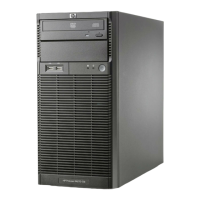
Describes the components located on the front panel of the server.
Details the LEDs and buttons on the server's front panel and their functions.
Explains the LEDs on the Systems Insight Display and their meanings.
Identifies and describes the components located on the rear panel of the server.
Details the LEDs on the server's rear panel and their statuses.
Provides a diagram and list of components on the server's system board.
Describes the location and numbering of DIMM slots for memory installation.
Explains the function of the ten-position system maintenance switch for configuration.
Describes the Non-Maskable Interrupt (NMI) feature for crash dump logging.
Explains the numbering scheme for SAS and SATA hard drive bays.
Details the LEDs on SAS and SATA hard drives and their status meanings.
Provides a table interpreting combinations of SAS/SATA drive LEDs.
Identifies the server's fans and their configurations (redundant/primary).
Explains the LEDs on the battery pack for cache module status.
Details the LEDs on the Flash-Backed Write Cache (FBWC) module.
Lists the connectors on the power supply backplane.
Describes jumper settings for drive cage configuration.
Instructions for turning on the server.
Procedures for safely shutting down and powering off the server.
Steps for unlocking and removing the server's tower bezel.
Instructions for extending the server from a rack for access.
Steps to remove the server's internal access panel.
Procedure for removing cooling fans 1 through 4.
Procedure for removing cooling fan 5.
Steps for removing the battery or capacitor pack for cache modules.
Instructions for removing the air baffle for component access.
Procedure for removing the server's fan cage assembly.
Steps to remove a blank filler from the media bay.
Procedure for removing the DVD-ROM drive from the server.
Steps to remove a blank filler from the hard drive cage.
Information on HP Care Pack services for server setup and support.
Guidance on resources for planning server rack installations.
Requirements for optimal operating conditions for the server.
Details required clearance and ventilation for server installation.
Specifies the recommended ambient operating temperature ranges.
Guidelines for electrical power installation and safety.
Procedures for ensuring proper electrical grounding of the server.
Safety warnings and precautions related to rack installation and stability.
General safety warnings and cautions for handling the server.
Lists items typically found in the tower server shipping carton.
Lists items typically found in the rack server shipping carton.
General guidance on installing optional hardware before server initialization.
Step-by-step instructions for setting up the server in a tower configuration.
Procedures for installing the server into various types of racks.
Steps for powering on, configuring, and initializing the server.
Guidance on installing supported operating systems on the server.
Instructions on how to register the server with HP.
Information and procedures for installing or replacing server processors.
Detailed steps for installing a processor into its socket.
Overview of supported memory types, speeds, and configurations.
Explains the server's memory architecture, channels, and slots.
Understanding DIMM ranks for memory configuration and protection.
How to identify DIMM characteristics from their labels.
Describes Advanced ECC, Mirrored Memory, and Lockstep memory modes.
Lists maximum memory capacities for RDIMMs based on rank.
Lists maximum memory capacities for UDIMMs.
Details the Advanced ECC memory protection mode.
Explains the Lockstep memory protection mode for error handling.
Describes the Online Spare memory protection feature.
Guidelines for populating DIMM slots across different AMP modes.
Specific population guidelines for Advanced ECC mode.
Population order for multi-processor Advanced ECC configurations.
Population order for single-processor Advanced ECC configurations.
Guidelines for populating DIMM slots in Lockstep memory mode.
Population order for single-processor Lockstep memory configurations.
Population order for multi-processor Lockstep memory configurations.
Guidelines for configuring Online Spare memory.
Step-by-step instructions for installing a DIMM into the server.
Explains the rules and behavior of redundant fans in the server.
Procedures for installing redundant fan modules into the server.
Information on configuring power supplies, including label color and output capacity.
Information on configuring power supplies, including label color and output capacity.
Guidance on calculating power supply needs for system configurations.
Steps to install a second hot-plug power supply for redundancy.
Procedure for installing a SAS hard drive into a hot-plug bay.
Procedure for installing a SAS hard drive into a hot-plug bay.
Steps for safely removing a SAS hard drive from a hot-plug bay.
Instructions for installing an eight-bay SFF drive cage in bay 2.
Instructions for installing an eight-bay SFF drive cage in bay 2.
Instructions for installing an eight-bay SFF drive cage in bay 3.
Steps for installing a six-bay LFF backplane in bay 1.
Steps for installing a six-bay LFF backplane in bay 1.
Steps for installing a six-bay LFF backplane in bay 2.
Procedure for installing a two-bay LFF drive cage.
Procedure for installing a two-bay LFF drive cage.
Instructions for installing a half-height device in a removable media bay.
Instructions for installing a half-height device in a removable media bay.
Instructions for installing a full-height device in a removable media bay.
Procedure for installing a slimline optical drive.
General steps for installing PCIe expansion boards.
Procedure for installing the 10GbE module onto an adapter.
Procedure for installing the 10GbE module onto an adapter.
Steps for installing a storage controller card.
Procedure for installing a cache module for write cache.
Procedure for installing a cache module for write cache.
Steps for installing the battery or capacitor pack for cache modules.
Procedure for installing the SAS Expander Card.
Instructions for installing a graphics adapter in a PCIe slot.
Steps to convert the server from tower to rack form factor.
Procedure for installing the TPM board onto the system board.
Procedure for installing the TPM board onto the system board.
Guidance on saving and managing BitLocker recovery keys/passwords.
Steps to enable the TPM functionality via RBSU and the OS.
General guidelines for connecting storage devices.
Diagrams and descriptions for server data cable connections.
Detailed diagrams for connecting SAS hard drives to controllers.
Cabling diagrams for the two-bay LFF drive cage.
Cabling diagrams for six-bay LFF backplanes.
Cabling diagrams for eight-bay SFF drive cages.
Diagrams illustrating SAS expander card connections.
Cabling for optical drives and media devices.
Cabling specific to the DVD-ROM drive.
Cabling specific to the slimline optical drive.
Diagrams for basic server power connections.
Diagrams for maximum server power connections.
Power cabling diagrams for hard drive cages.
Cabling for front panel connectors like USB and video.
Cabling for battery and capacitor packs for write cache.
Overview of tools for server configuration like SmartStart and RBSU.
Description of SmartStart for server deployment and configuration.
Information on the toolkit for building automated server deployments.
Details the RBSU for configuring system devices and features.
Instructions on how to navigate and use the RBSU utility.
Explains the automatic system configuration process during initial boot.
Describes the boot options screen and available keys.
Information on using BIOS Serial Console for remote configuration.
Explains Advanced Memory Protection (AMP) modes like ECC, Mirrored, Lockstep.
Steps to configure the Mirrored Memory protection mode.
Steps to configure the Advanced ECC memory protection mode.
Steps to configure the Lockstep memory protection mode.
Description of the ACU browser-based utility for array management.
Using ORCA utility for creating logical drives and RAID configurations.
Procedure to re-enter serial number and product ID after system board replacement.
Explains the ASR feature for system restarts after errors.
Information on using ROMPaq for system firmware upgrades.
Details the iLO 2 subsystem for remote server management and health.
Instructions for using the System Erase Utility to reset the system.
Explains the server's capability for redundant ROM images.
Benefits of ROM flashing and safety features.
Information on USB support, including legacy support.
Overview of diagnostic utilities available for the server.
Description of the Insight Diagnostics tool for system testing.
Explains the survey functionality for gathering hardware/software info.
How to view recorded system events in the IML.
Information on HP Insight Remote Support software.
Guidance on maintaining the system with updated drivers and software.
How to install and update device drivers for the server.
Tools for managing software versions and updates.
Information about PSPs for OS-specific driver bundles.
How to check supported OS versions.
Information about the Smart Update Firmware DVD.
Details HP SUM for intelligent firmware and software deployment.
Information on HP's notification service for product changes.
Details on HP Care Pack Services for extended support.
Provides links to the HP ProLiant Servers Troubleshooting Guide.
Essential steps to perform before starting server diagnostics.
Safety precautions to read before troubleshooting server components.
Guidance on collecting information about server symptoms.
Steps to prepare the server environment for diagnosis.
Guidelines for troubleshooting processor-related issues.
Procedures for reducing the server to its minimal configuration for troubleshooting.
Checks and actions for identifying and resolving loose cable connections.
Where to find the latest service notifications from HP.
Information on server health LEDs and their meanings.
Introduction to the troubleshooting flowchart section.
The initial flowchart to begin the server diagnostic process.
A generic flowchart for troubleshooting unknown or unclassified problems.
Flowchart for diagnosing issues related to server power-on.
Flowchart for diagnosing problems during the Power-On Self Test (POST).
Flowchart for troubleshooting issues with operating system boot failures.
Flowchart for diagnosing server faults indicated by management agents or LEDs.
Reference for understanding POST error messages and beep codes.
Steps to remove the server's real-time clock battery.
Procedure for physically removing the battery.
Explains regulatory model numbers and their importance.
FCC Part 15 notice regarding RF emissions and device classification.
How to interpret the FCC rating label on the device.
FCC compliance statement for Class A digital devices.
FCC compliance statement for Class B digital devices.
FCC Part 15 compliance statement and contact information.
FCC notification regarding unauthorized modifications.
Requirements for using shielded cables to maintain FCC compliance.
Compliance notices for Class A and Class B equipment in Canada.
CE marking compliance with EU directives and standards.
Guidelines for proper disposal of waste electrical and electronic equipment.
Compliance notices specific to Japan.
Compliance notices from Taiwan's BSMI.
Compliance notices for Class A and Class B equipment in Korea.
Compliance notices for Class A equipment in China.
Compliance marking for applicable products in Vietnam.
Safety information regarding Class 1 Laser Products in optical devices.
Notice related to battery replacement.
Notice regarding dry battery recycling in Taiwan.
Power cord statement specific to Japan.
Acoustic noise level statement for Germany.
Precautions to prevent damage from static electricity.
Methods and equipment for proper grounding to prevent ESD.
Operating and shipping environmental conditions for the server.
Physical dimensions and weight specifications for rack and tower models.
Input and output specifications for the server's power supplies.
Information to have ready before contacting HP support.
How to find HP authorized resellers and technical support contact details.
Information on HP's Customer Self Repair program for parts replacement.
| Processor | Intel Xeon 5500 and 5600 series |
|---|---|
| Processor Sockets | 2 |
| Memory | Up to 192 GB DDR3 |
| Memory Slots | 18 DIMM slots |
| Form Factor | 5U Tower |
| Storage | Up to 16 SFF drives or 8 LFF drives |
| Expansion Slots | 6 total: 2 x8 PCIe Gen2, 2 x4 PCIe Gen2, 1 x8 PCIe Gen2, 1 x4 PCI |
| Network | Embedded Dual Port Gigabit Ethernet |
| Power Supply | Redundant hot-plug power supplies |
| Operating System Support | Windows, RHEL, SLES, VMware |