Component identification 14
Item Description
26
Slot 10 PCIe2 x8 (8, 4, 2, 1)
27
Internal USB connector
28
Processor socket 2
29
Processor 2 DIMM slots
30
Power supply connector
31
Processor socket 1 (populated)
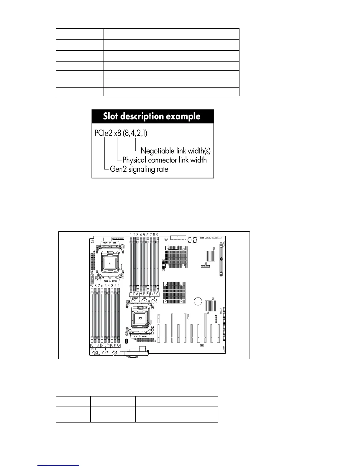
DIMM slots
DIMM slots are numbered sequentially (1 through 9) for each processor. The supported AMP modes use the
letter assignments for population guidelines.
System maintenance switch
The system maintenance switch (SW1) is a ten-position switch that is used for system configuration.
Position Description Function
S1
iLO security Off = iLO security is enabled.
On = iLO security is disabled.
 Loading...