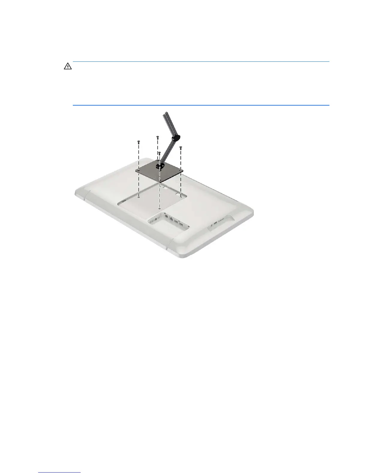
4. Align the screw holes on the mounting fixture with the VESA holes on the back of the all-in-one,
and then insert four 10 mm screws (not provided) through the holes on the mounting fixture and
into the mounting holes on the all-in-one.
CAUTION: This all-in-one supports the VESA industry standard 100 mm mounting holes. To
attach a third-party mounting solution to the all-in-one, four 4 mm, 0.7 pitch, and 10 mm long
screws are required. Longer screws must not be used because they may damage the all-in-one.
It is important to verify that the manufacturer’s mounting solution is compliant with the VESA
standard and is rated to support the weight of the all-in-one. For best performance, it is important
to use the power and video cables provided with the all-in-one.
6 Chapter 2 Setting up the hardware