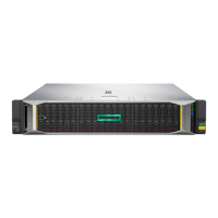
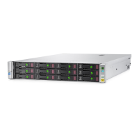
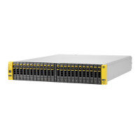
Figure 13 StoreEasy 1x50 with the P441 controller in a dual domain configuration (best
fault tolerance)
1. P441 controller
2. Connection from P441 controller to port 2 of I/O module B on top of the disk enclosures in Group 2
3. Group 1 of 4 D2000/D3000 enclosures
4. Group 2 of 4 D2000/D3000 enclosures
5. Connection from P441 controller to port 2 of I/O module A on top of the disk enclosures in Group 1
6. Connections between the disk enclosures in Group 1
7. Connections between the disk enclosures in Group 2
Figure 14 (page 21) illustrates best performance. The difference between this cabling and fault
tolerance cabling is that the beginning and ending connections from the controller to a disk
enclosure are always to the first disk enclosure in the group. Essentially, the request from the
controller to a disk enclosure moves faster because it does not have to travel through a series
of disk enclosures. However, this cabling does not provide fault tolerance. If an I/O module in
the first disk enclosure fails, you will lose access to all disk enclosures in the group.
NOTE: The cabling diagram in Figure 14 (page 21) is exactly the same for the StoreEasy 1440
and 1640 using the P822 controller.
20 Setup and install
 Loading...

