EL-MF877-00 Page 2
Template Revision B
PSG instructions for this template are available at EL-MF877-01
Components, parts and materials containing
refractory ceramic fibers
0
Components, parts and materials containing
radioactive substances
0
2.0 Tools Required
List the type and size of the tools that would typically be used to disassemble the product to a point where components
and materials requiring selective treatment can be removed.
Tool Description Tool Size (if
applicable)
Philips Screw Driver #2
Torx Head Screw Driver Large
Wrench M4
3.0 Product Disassembly Process
3.1 List the basic steps that should typically be followed to remove components and materials requiring selective treatment:
1. Bezel-Manual removal
2. Removal the battery fixed plate
3. Battery connector-Manual disconnection
4. Removal of cover with Hex head screw drive on the rear of the unit
5. Pull the battery pack out from the battery room,disconnect the battery pack with PCB
6. Removal the rear panel with Philips Screw Driver, disconnect the wire between the rear panel and PCB
7. Removal the PCB from the main frame with Philips screw driver
8. Remove the AVR from the main frame with a M4 wrench
3.2 Optional Graphic. If the disassembly process is complex, insert a graphic illustration below to identify the items
contained in the product that require selective treatment (with descriptions and arrows identifying locations).
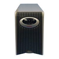
(1) The Component location of T750/T1000 UPS Unit
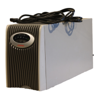
(2) Capacitor Location(diameter over 2.5cm)
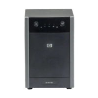
(3) Battery Pack disassembly
 Loading...