6 Chapter 3. Setting Up the Monitor ENWW
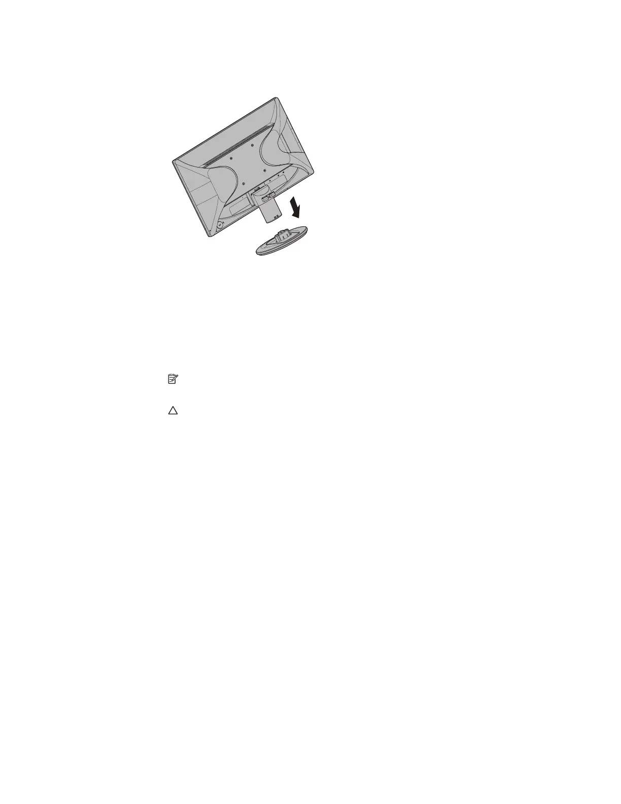
4. Remove the base and slide it away from the bottom of the monitor.
Figure 3-4 Sliding the base away from the monitor
5. Four threaded holes are exposed on the back panel of the monitor. These holes
are for screws to attach the swing arm or other mounting fixture to the back of the
monitor.
6. Follow the instructions included with the mounting fixture to ensure that the
monitor is safely attached. The four threaded holes that are on the back of the
panel are compliant with the VESA standard for mounting flat-panel monitors.
7. Attach a swing arm or other mounting fixture.
NOTE: This apparatus is intended to be supported by UL or CSA Listed wall mount
bracket.
CAUTION: This monitor supports the VESA industry standard 100 mm mounting holes.
To attach a third-party mounting solution to the monitor, four 4 mm, 0.7 pitch, and 10 mm
long screws are required. Longer screws must not be used because they may damage the
monitor. It is important to verify that the manufacturer’s mounting solution is compliant with
the VESA standard and is rated to support the weight of the monitor display panel. For best
performance, it is important to use the power and video cables provided with the monitor.