Do you have a question about the HP Z2 Tower G5 and is the answer not in the manual?
Detailed steps for removing components and the external enclosure.
Illustrations showing selective treatment item locations and removal steps.
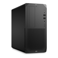
This document outlines the disassembly process for the HP Z2 Tower G5 Workstation, primarily for end-of-life recyclers and treatment facilities, ensuring compliance with EU directive 2012/19/EC (WEEE) regarding selective treatment of components and materials. The instructions facilitate the removal of specific parts that require special handling due to their composition or potential environmental impact.
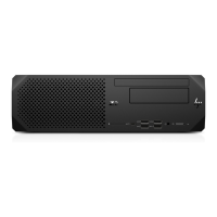
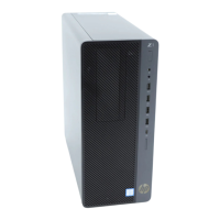
The workstation is designed with a focus on modularity to aid in servicing and end-of-life recycling. Its internal layout allows for relatively straightforward access to key components. The disassembly process begins with opening the access panel, which is a fundamental step for any internal maintenance or component removal. This initial step is crucial for gaining entry to the system's core. Following this, the front bezel can be removed from the chassis, providing further access to the internal structure and components mounted at the front.
A significant aspect of the workstation's design involves its graphic card, which is secured by a latch. The process details disconnecting the cable from the graphic card and then pressing its latch to unplug it, indicating a tool-less or minimal-tool removal mechanism for this component. This design choice simplifies upgrades or replacements of the graphic card, a common component for performance enhancements.
The optical disc drive (ODD) is similarly designed for ease of removal. The instructions specify pressing the ODD's latch on the ODD cage, followed by disconnecting both the power and SATA cables. Subsequently, the ODD can be removed from its cage. This modular approach extends to the hard disk drive (HDD) system. After removing the ODD, the process involves loosening screws on an iron plate, removing the plate, and then loosening screws to remove the HDD from its cage. Disconnecting the HDD's power and SATA cables precedes the removal of the entire driver cage from the chassis. These steps highlight a layered and organized internal structure, where components are grouped and secured in dedicated cages.
The motherboard (MB) serves as the central hub for many connections. The instructions emphasize disconnecting all cables from the MB, including the system fan cable, before proceeding with the removal of the system fan itself. The system fan is secured with screws, requiring a PH1 screwdriver for its removal. This indicates that while some components might have tool-less latches, others still rely on standard fasteners.
The cooling system, particularly the cooler and its fan, is also addressed. The process involves using a T-15 screwdriver to loosen the screws of the cooler, followed by a PH1 screwdriver to loosen the screws of the fan, and then separating the fan from the cooler. This separation is important for individual component replacement or cleaning.
Memory modules are designed for easy removal from the motherboard, typically involving pressing retention clips. The CPU, a critical component, requires rotating a handle to open its socket and then removing it from the board. The system board also houses a battery, which needs to be removed. Other components like the speaker and WLAN M.2 Card are also part of the disassembly sequence, often secured with screws (T-15 screwdriver for the WLAN M.2 Card) or simple connectors.
The power supply unit (PSU) is another key component with a detailed removal process. After removing the motherboard from the chassis, the instructions detail using a T-15 screwdriver to remove screws on the PSU chassis, disconnecting the PSU cable from the motherboard, and then removing the PSU from the chassis. Further steps involve using a PH1 screwdriver to remove screws for the PSU, removing a cover, and then removing additional screws (FG screw, AC inlet & Fan screw) to access the internal PCB of the PSU. The final step for the PSU involves heating the solder of electrolytic capacitors greater than 2.5 cm in diameter or height to remove them, highlighting a specific selective treatment requirement for these components.
Throughout the disassembly process, various tools are specified: a Hexagon Screw Driver (T-15), a Crisscross Screw Driver (PH1), and an Electric Iron (QUICK 310). The use of these standard tools suggests that the workstation is designed to be serviceable using commonly available equipment.
The document also lists items requiring selective treatment, categorized by their material or function. These include printed circuit boards (PCBs) or printed circuit assemblies (PCAs) with a surface greater than 10 sq cm, various types of batteries (excluding Li-Ion, and Li-Ion batteries themselves), mercury-containing components, liquid crystal displays (LCDs) with a surface greater than 100 sq cm, cathode ray tubes (CRTs), capacitors/condensers containing PCB/PCT, electrolytic capacitors/condensers measuring greater than 2.5 cm in diameter or height, external electrical cables and cords, gas discharge lamps, and plastics containing brominated flame retardants weighing > 25 grams. The inclusion of a "Quantity of items included in product" column for these items underscores the importance of tracking and properly managing these materials during the recycling process.
The workstation's design facilitates the removal of components containing toner and ink, asbestos, refractory ceramic fibers, and radioactive substances, should they be present, although specific quantities are not listed for these in the provided example. This comprehensive approach to disassembly and material identification ensures that the workstation can be responsibly recycled, minimizing environmental impact and recovering valuable materials. The detailed, step-by-step instructions, complemented by graphic illustrations for complex steps, make the process accessible for trained personnel, ensuring efficient and safe handling of the product at its end-of-life.
| Chipset | Intel W480 |
|---|---|
| Memory | Up to 128 GB DDR4-2933 ECC or non-ECC SDRAM |
| Processor Options | Intel Core i5, i7, i9; Intel Xeon W-1200 series |
| Storage Options | M.2 SSD, 2.5" SSD/HDD, 3.5" HDD |
| Graphics | Integrated Intel UHD Graphics 630; NVIDIA Quadro P400, P620, P1000, P2200, RTX 4000; AMD Radeon Pro WX 3200 |
| Operating System | Windows 10 Pro, Windows 10 Home, Linux |
| Expansion Slots | 1 PCIe 3 x16, 1 PCIe 3 x4 |
| Rear Ports | USB 3.1 Gen 2 Type-A, USB 2.0 |
| Power Supply | 500 W internal power supply |
| Dimensions | 356 x 169 x 385 mm |
| Front Ports | USB 3.1 Gen 2 Type-C, headphone/microphone combo jack |