Do you have a question about the HP Z2 Mini G5 and is the answer not in the manual?
PCBs/PCAs with surface area > 10 sq cm.
All Li-Ion batteries, including detachable ones.
Components containing mercury, e.g., lamps.
Backlit displays with gas discharge lamps.
Plastics > 25g, excluding PCBs/PCAs.
Asbestos-containing parts.
Phillips head screwdriver, size T8.
Phillips head screwdriver, size T10.
Phillips head screwdriver, size T15.
Steps to remove the top cover.
Steps to remove the HDD.
Steps to remove CPU/GPU fan.
Steps to remove CPU/GPU thermal module.
Steps to remove M/B battery.
This document outlines the disassembly procedures for the HP Z2 Mini G5 Workstation, specifically models TPC-1046-DM-180 and TPC-1046-DM-280. It is primarily intended for end-of-life recyclers and treatment facilities to ensure the proper removal of components and materials requiring selective treatment, as defined by EU directive 2002/96/EC (WEEE). Recyclers are advised to sort plastic materials based on their ISO 11469 marking codes for efficient recycling.
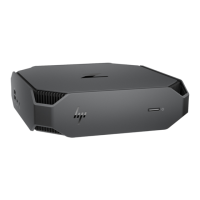
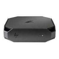
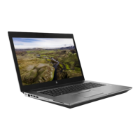
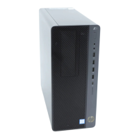
The HP Z2 Mini G5 Workstation is a compact computing device designed for professional use, offering robust performance in a small form factor. Its modular design allows for the selective removal of various internal components, which is crucial for both maintenance and end-of-life recycling. The disassembly process focuses on isolating specific parts that require special handling due to their material composition or potential environmental impact.
Key components that are subject to selective treatment include Printed Circuit Boards (PCBs) or Printed Circuit Assemblies (PCAs) with a surface greater than 10 sq cm, various types of batteries (excluding Li-Ion, which are handled separately), Li-Ion batteries (including detachable notebook keyboard batteries and RTC coin cells), mercury-containing components (such as lamps, display backlights, and switches), Liquid Crystal Displays (LCDs) with a surface greater than 100 sq cm, Cathode Ray Tubes (CRTs), capacitors/condensers containing PCB/PCT, electrolytic capacitors/condensers measuring greater than 2.5 cm in diameter or height, external electrical cables and cords, and gas discharge lamps. The workstation also contains plastics with brominated flame retardants (weighing over 25 grams), and other components containing toner, ink, asbestos, refractory ceramic fibers, and radioactive substances, all of which require specific handling during disassembly.
The disassembly instructions detail the removal of various internal modules, including the top cover, Hard Disk Drive (HDD), HDD screws, CPU and GPU fans, CPU/GPU thermal modules, VGA/B components (for both 65W and 125W configurations), thermal sponges, serial/B and USB/B components, Thunderbolt (TBT) board, hood sensor, HDD cable, DDR (Double Data Rate) memory and its shielding can, Solid State Drive (SSD), CPU, speaker, LED and power set, DDR cover, DDR modules, antenna caps, antennas, WLAN card, and the main motherboard (M/B) and its battery. Each step is designed to systematically isolate these components for proper disposal or recycling.
The primary "usage" feature described in this document pertains to the disassembly process itself, rather than the operational use of the workstation. The instructions are structured to guide technicians through a methodical breakdown of the device. This systematic approach ensures that all components requiring selective treatment are identified and removed correctly.
The process begins with the removal of the top cover, which is secured by a detachable button. Once the top cover is off, access is gained to internal components. The HDD, if present, is secured by a screw and then removed in an oblique direction, followed by the detachment of its cable. Specific torque forces are provided for screw removal, emphasizing precision to prevent damage during disassembly. For instance, HDD set screws require a torque force of 2.5 +/- 0.2 kgf.cm, while MXM screws for VGA/B components require 1.5 +/- 0.2 kgf.cm.
Fans (CPU and GPU) are removed by lifting them, detaching their connectors, and then taking them out. Thermal modules for the CPU and GPU are secured by screws, and specific instructions are given to align the driver head first to prevent the screw from sliding. Thermal sponges, which are part of the cooling system, are also removed.
Peripheral boards like the serial/B, USB/B, and TBT boards are detached by removing their screws and then carefully disconnecting their cables or lifting them vertically. The hood sensor is removed by detaching its housing from the middle body and then its cable. The HDD cable is disconnected from the motherboard.
DDR memory modules and their shielding cans are removed by first detaching the shielding can (which may involve peeling off black mylar on both sides) and then opening the DDR connector arms to release the modules. SSDs are removed by unscrewing them and then detaching them. The CPU removal involves using a specific fixture to clamp it, followed by baking to the connecting rod, highlighting the need for specialized tools for this sensitive component.
Speakers are removed by detaching their connector and then releasing their housing. The LED and power set involves disassembling the LED lens, removing cables, pulling out the connector, and taking out the power housing and thermal sensor. The DDR cover is removed by pushing a hook and then taking it off. WLAN cards and antennas are also systematically removed by unscrewing them and detaching their connectors.
Finally, the motherboard (M/B) is removed by unscrewing it (with a specified torque force of 3.0 +/- 0.2 kgf.cm) and then carefully lifting it from the chassis in an oblique direction, paying attention to specific positions to avoid damage. The M/B battery is then removed by releasing its elastic arm.
While the document focuses on end-of-life disassembly, the detailed step-by-step instructions and the emphasis on specific tools and torque values inherently support maintenance activities. The ability to selectively remove and replace components is a core aspect of device maintenance. For example, if a component like the HDD, CPU fan, or DDR module needs to be replaced, these instructions provide the exact sequence and precautions necessary for safe and effective removal and reinstallation.
The "Tools Required" section lists essential tools such as T8, T10, and T15 screwdrivers, along with "Half finger insert" and "CPU assemble fixture," indicating that specialized tools are necessary for certain tasks. The mention of torque forces for screws (e.g., 2.5 +/- 0.2 kgf.cm for HDD screws, 1.5 +/- 0.2 kgf.cm for MXM, serial/B, USB/B, TBT, and WLAN card screws, and 3.0 +/- 0.2 kgf.cm for M/B screws) is critical for both disassembly and reassembly. Using the correct torque ensures that components are securely fastened without being over-tightened, which could strip threads or damage parts, or under-tightened, which could lead to loose connections or component failure.
The warnings about aligning the driver head first when taking screws to prevent sliding, or not shaking the TBT board from left to right to prevent scraping, are vital for preventing damage during both removal and reinstallation. Similarly, the instruction to lift the HDD in an oblique direction or to use a fixture for CPU removal highlights best practices that extend to maintenance procedures.
The document also includes "Notice: Please inform production line leader or master if you found any abnormal.." at the bottom of each page, which serves as a quality control mechanism. This feedback loop is crucial for identifying and addressing issues in the manufacturing or disassembly process, ensuring continuous improvement in product design for easier maintenance and recycling. The revalidation date (04-01-2018) and revision history (e.g., "add remove the M/B battery whole upda" on 2020/7/1) indicate that the instructions are regularly reviewed and updated, reflecting ongoing efforts to refine procedures for efficiency and safety. This commitment to updated documentation directly benefits maintenance personnel by providing the most current and accurate guidance.
| Tjunction | 100 °C |
|---|---|
| Processor cache | 16 MB |
| Processor cores | 8 |
| System bus rate | 8 GT/s |
| Processor family | Intel® Core™ i7 |
| Processor socket | LGA 1200 (Socket H5) |
| Processor threads | 16 |
| Processor codename | Comet Lake |
| Processor frequency | 2.9 GHz |
| Processor cache type | L3 |
| Processor lithography | 14 nm |
| Processor manufacturer | Intel |
| PCI Express slots version | 3.0 |
| Processor boost frequency | 4.8 GHz |
| Processor operating modes | 64-bit |
| PCI Express configurations | 1x16, 2x8, 1x8+2x4 |
| Thermal Design Power (TDP) | 65 W |
| Number of processors installed | 1 |
| Memory types supported by processor | DDR4-SDRAM |
| Memory clock speeds supported by processor | 2933 MHz |
| Memory bandwidth supported by processor (max) | 45.8 GB/s |
| Maximum internal memory supported by processor | 128 GB |
| Chassis type | Mini PC |
| Product color | Black |
| Country of origin | China |
| Intel® vPro™ Platform Eligibility | - |
| ECC | No |
| Memory slots | 2x DIMM |
| Internal memory | 16 GB |
| Memory clock speed | 3200 MHz |
| Maximum internal memory | 64 GB |
| Memory layout (slots x size) | 2 x 8 GB |
| SSD capacity | The Solid State Drive's storage capacity in Gigabytes. |
| SSD interface | NVMe |
| Storage media | SSD |
| SSD memory type | TLC |
| Total storage capacity | 512 GB |
| Product type | Workstation |
| Motherboard chipset | Intel W480 |
| HP segment | Business |
| HP Security tools | HP Secure Erase; HP Sure Click; HP Sure Sense; HP Sure Start Gen6; HP Sure Run Gen3; HP Sure Recover Gen3; HP BIOSphere Gen6; HP Sure Admin; Hood Sensor Optional Kit; HP Client Security Manager Gen6 |
| HP Software provided | HP PC Hardware Diagnostics UEFI; HP Performance Advisor; HP PC Hardware Diagnostics Windows; HP Image Assistant; HP Manageability Integration Kit |
| Cabling technology | 10/100/1000Base-T(X) |
| Ethernet LAN data rates | 10, 100, 1000 Mbit/s |
| DisplayPorts quantity | 3 |
| USB 2.0 ports quantity | 0 |
| USB 3.2 Gen 2 (3.1 Gen 2) Type-A ports quantity | 4 |
| USB 3.2 Gen 2 (3.1 Gen 2) Type-C ports quantity | 2 |
| Operating system installed | Windows 10 Pro for Workstations |
| Discrete GPU manufacturer | NVIDIA |
| On-board graphics card ID | 0x9BC5 |
| Discrete graphics card model | NVIDIA Quadro T1000 |
| On-board graphics card model | Intel® UHD Graphics 630 |
| Discrete graphics card memory | 4 GB |
| Discrete graphics memory type | GDDR5 |
| On-board graphics card OpenGL version | 4.5 |
| On-board graphics card base frequency | 350 MHz |
| On-board graphics card DirectX version | 12.0 |
| On-board graphics card dynamic frequency (max) | 1200 MHz |
| Power supply | 280 W |
| Scalability | 1S |
| Processor ARK ID | 199316 |
| Processor package size | 37.5 x 37.5 mm |
| Supported instruction sets | SSE4.1, SSE4.2, AVX 2.0 |
| Thermal solution specification | PCG 2015C |
| Graphics card interface | PCIe x16 |
| Harmonized System (HS) code | 84715000 |
| Width | 216 mm |
|---|---|
| Height | 58 mm |
| Weight | 2100 g |