EasyManua.ls Logo

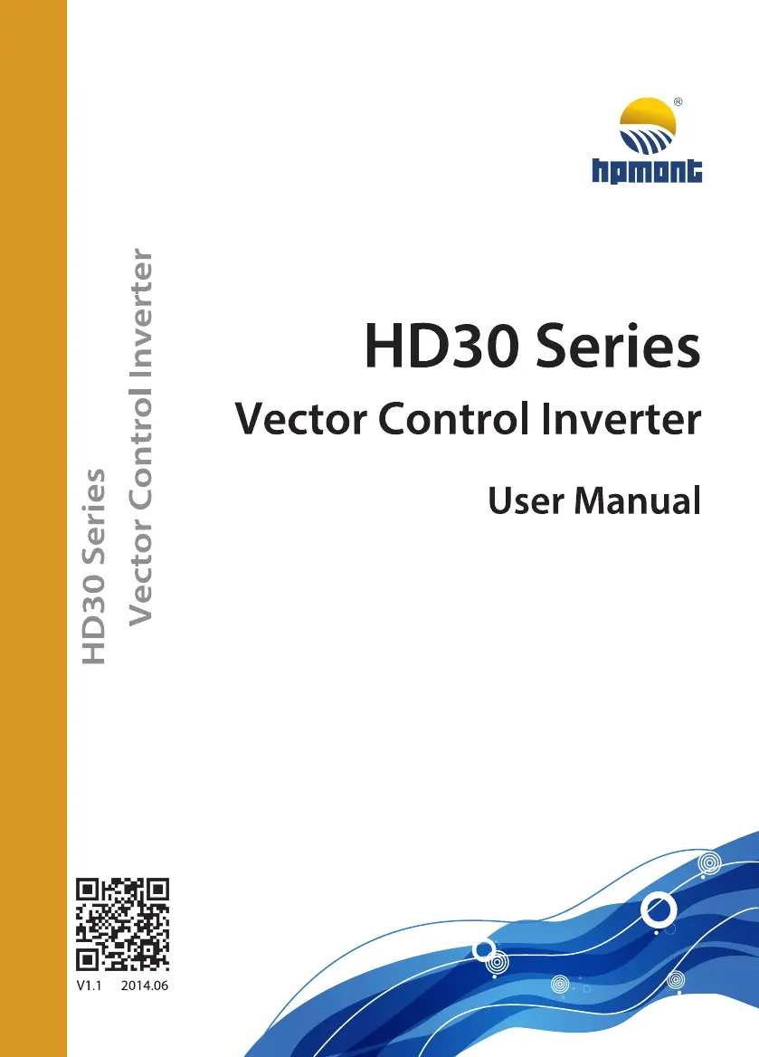
hpmont HD30-4T022G/030P - User Manual

hpmont HD30-4T022G/030P
215 pages
Print Icon
To Next Page IconTo Next Page
Loading...

Table of Contents

Questions and Answers

  • M
    Mrs. Cynthia HuangSep 8, 2025
    What does fault of input phase mean on hpmont HD30-4T022G/030P?
    • J
      Jessica KimSep 8, 2025
      If your hpmont three-phase input inverter shows a fault of input phase, it means a phase loss fault has occurred to the power input; check the three-phase power input. If this doesn't solve your problem, seek technical support.
  • B
    Brandon WalkerAug 23, 2025
    Why is my hpmont HD30-4T022G/030P showing DC bus over voltage during acceleration?
    • L
      Larry VargasAug 23, 2025
      DC bus over voltage during acceleration in your hpmont Inverter can occur due to several reasons. The input voltage might be too high, so check the power input. Also, the deceleration time could be too short; adjust it using parameters F03.02, F03.04, F03.06, and F03.08. Improper wiring can also lead to overvoltage, so inspect the wiring and ensure the inverter is wired correctly. If an instant stop occurred and the motor restarted, set the start mode to speed tracking (F02.00=2). Finally, ensure that the braking devices are properly selected according to the user manual's recommendations.
  • M
    Matthew DavisAug 25, 2025
    How to fix hpmont Inverter output overcurrent during acceleration?
    • M
      Melissa CoxAug 25, 2025
      To resolve an hpmont Inverter output overcurrent during acceleration, consider these potential causes. Ensure proper connection between the inverter and the motor. Verify and correct motor parameters using F08.00, F08.04, F13.01, and F13.05. If the inverter's rating is too small, select one with a higher rating. Also, adjust the acceleration and deceleration times using parameters F03.01 and F03.08. If an instant stop occurs and the motor restarts, set the start mode to speed tracking (F02.00=2).
  • G
    George SimsAug 26, 2025
    What causes a motor overload on my hpmont Inverter?
    • M
      Melanie WadeAug 27, 2025
      A motor overload on your hpmont Inverter can stem from several causes. An improper setting of the V/f curve can be a factor, so adjust it using parameters F09.00-F09.06. Also, a low mains supply voltage can contribute, so check the power input. If the motor runs for a long time with a heavy load at low speed, consider using a special motor designed for such conditions. Ensure the motor’s overload protection factor is properly set. Finally, check for a blocked torque or an excessively heavy load, and inspect the load and mechanical transmission devices.
  • A
    Angela SantiagoAug 27, 2025
    What to do if my hpmont HD30-4T022G/030P shows DC bus undervoltage?
    • C
      Craig RamosAug 28, 2025
      DC bus undervoltage on your hpmont Inverter can be caused by a few things. First, check the input power voltage to ensure it is not too low. If it is, correct it. Also, improper wiring can lead to undervoltage, so verify the wiring and ensure the inverter is wired correctly. Note that this can be a normal status during powering on and powering off.
  • J
    jmartinezSep 22, 2025
    What does access fault of control board EEPROM mean on hpmont Inverter?
    • C
      Catherine MccormickSep 22, 2025
      An access fault of the control board EEPROM on your hpmont Inverter indicates a memory circuit fault of the control board EEPROM. Contact the supplier for repairing.
  • S
    Stephanie WestSep 16, 2025
    What to do if there is a fault of current detection circuit on hpmont HD30-4T022G/030P Inverter?
    • E
      Eric HurstSep 16, 2025
      If there is a fault of the current detection circuit on your hpmont Inverter, indicating that the current detection circuit is damaged, contact the supplier for repair.
  • D
    Daniel JamesSep 18, 2025
    What does access fault of display panel EEPROM mean on hpmont HD30-4T022G/030P Inverter?
    • M
      melissa28Sep 18, 2025
      An access fault of the display panel EEPROM on your hpmont Inverter indicates a memory circuit fault of the display panel EEPROM. You can try replacing the display panel. If the problem persists, contact the supplier for repairing.
  • D
    David PowellSep 7, 2025
    What causes parameters auto-tuning fault on hpmont HD30-4T022G/030P?
    • O
      Olivia TurnerSep 7, 2025
      A parameters auto-tuning fault on your hpmont Inverter can occur if the parameter auto-tuning times out, so check the motor’s connection. Ensure that you input the correct motor parameters (F08.00, F08.04, F13.01, F13.05). If problems persist, seek technical support.
  • J
    Jill LoveSep 4, 2025
    Why am I getting a fault setting of parameters error on my hpmont Inverter?
    • A
      Alexandra SullivanSep 4, 2025
      A fault in the parameter settings of your hpmont Inverter can occur if the power rating between the motor and inverter is too different; select an inverter with a suitable power rating. It can also be due to improper setting of motor parameters, so set the correct values for motor parameters (F08.00, F08.04, F13.01, F13.05).

Summary

QUICK START for USER MENU of GROUP U

QUICK START for HD30 OPERATION

Control the start;stop via terminals and set the running frequency via display panel

Control the start;stop via terminals and set the running frequency via analogue

Control the start;stop via terminals and set the running frequency via communication

Chapter 1 Safety Information and Precautions

1.3 Installation Limitation

Outlines restrictions on connecting components to the output and inverter usage limitations.

Chapter 2 Product Information

2.3 Specifications

Lists the electrical, performance, and characteristic specifications of the HD30 series inverters.

2.4 Ratings

Presents detailed electrical ratings for various models of HD30 series inverters.

Chapter 3 Mechanical Installation

3.1 Installation Precautions

Provides essential safety precautions and warnings before starting the installation process.

3.2 Requirement for the Installation Site

Specifies environmental and site requirements for proper inverter installation and operation.

3.3 Installation Direction and Space Requirements

Details the recommended inverter mounting orientation and necessary clearance for cooling.

3.4 Dimensions and Mounting Size

Provides detailed physical dimensions and mounting hole specifications for the HD30 series.

3.5 Display Panel Installation and Dismantle

Explains the procedure for correctly installing and removing the inverter's display panel.

Chapter 4 Electrical Installation

4.1 Wiring Precautions

Lists critical safety precautions and guidelines for performing electrical wiring on the inverter.

4.2 Selection of Main Circuit Peripheral Devices

Recommends specifications for MCCBs, contactors, and cables based on inverter model.

4.3 Main Circuit Terminals and Wiring

Details the main circuit terminal layout and provides wiring diagrams for power connections.

4.4 Control Terminals and Wire Connection

Explains the control circuit terminals, wire jumper settings, and connection procedures.

4.5 Meet EMC Requirement of Installation

Provides guidelines for correct installation to meet Electromagnetic Compatibility (EMC) standards.

Chapter 5 Operation Instructions

5.1 Function Description

Introduces the inverter's core functions including command sources and frequency setting.

5.2 Operating Instructions

Covers display panel description, key functions, indicator meanings, and operation processes.

5.3 Initial Power On

Details the necessary checks and procedures before powering on the inverter for the first time.

Chapter 7 Troubleshooting

Fault alarm description and counter-measures

Lists common fault codes, possible reasons, and recommended counter-measures for troubleshooting.

Chapter 8 Maintenance

8.1 Daily Maintenance

Outlines daily checks for operating environment, inverter, and motor conditions.

8.2 Periodical Maintenance

Describes general inspection procedures and periodic checks for hidden problems.

8.3 Replacing Damaged Parts

Provides information on the lifespan and replacement criteria for common components like cooling fans.

Chapter 9 Options

9.5 Braking Unit and Braking Resistor Selection

Provides recommendations for selecting braking units and resistors based on motor power.

9.6 Reactor Selection

Lists recommended AC and DC reactors based on the inverter model and required parameters.

Appendix A Parameters

Appendix C Communication Protocol

4. Protocol Format

Explains the MODBUS RTU and ASCII frame formats for communication.

6. Protocol Function

Lists supported MODBUS function codes for parameter operations like reading and writing.

7. Address Mapping

Details the mapping of inverter parameters to MODBUS register addresses and control parameters.

hpmont HD30-4T022G/030P Specifications

General IconGeneral
ModelHD30-4T022G/030P
CategoryInverter
Rated Power22kW
Protection FeaturesOvervoltage, Undervoltage, Short Circuit
Storage Temperature-20°C to 60°C
Cooling MethodForced Air

Related product manuals