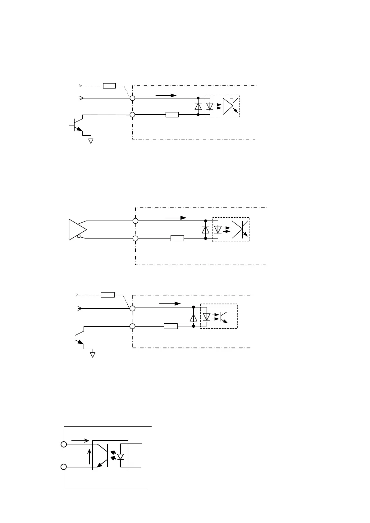
4.I/O circuit diagram
4-1 Command pulse or CW pulse (P+, P-), Direction Command or CCW pulse (D+, D-) Input
In case of Open collector driven
Note 1) When circuit is driven at + 24V, connect a resistor of 1 W, 2 kΩ (recommend) in series.
When using a resistor other than 2 kΩ, use the resistance value that satisfies the current value in the
figure.
Note 2) In case of Open collector driven, the cable length should be within 1m.
In case of Line driver driven
4-2 Excitation off (OFF) input
Note) When circuit is driven at + 24V, connect a resistor of 0.5W, 2 kΩ (recommend) in series.
When using a resistor other than 2 kΩ, use the resistance value that satisfies the current value in the
figure.
4-3 Alarm (ALM) Output
270Ω
5mA≦IL≦30mA
TLP291GB(東芝)
又は相当品
+5V
0V
IL
+24V
0.5W,2kΩ (注)
OFF+
OFF-
TLP281 GB( 東芝)
又は相当品
+
-
VCE
Io
Io ≦ 4mA
VCE ≦ 50Vmax
270Ω
+
-
AM26LS31相当品
P+,D+
P-,D-
2mA≦IL≦13mA
IL
TLP2358(東芝)又は相当品
270Ω
TLP2358(東芝)又は相当品
2mA≦IL≦13mA
IL
+
-
+5V
0V
P+,D+
P-,D-
+24V
0.5W,2kΩ(注1)
TLP2358 (Toshiba) or compatible parts
AM26LS31
or compatible parts
TLP2358 (Toshiba) or compatible parts
TLP281GB (Toshiba) or compatible parts
TLP291GB (Toshiba) or compatible parts