EasyManuals Logo

HPtec SD4030B3 User Manual

HPtec SD4030B3
24 pages
To Next Page IconTo Next Page
To Previous Page IconTo Previous Page
Page #9 background imageLoading...
Page #9 background image
3
3.Connector pin assignment
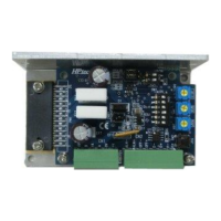
3-1 CN1
No.
Signal name
Definition
IN/OUT
6
/B
Motor Phase /B
OUT
5
B
Motor Phase B
OUT
4
/A
Motor Phase /A
OUT
3
A
Motor Phase A
OUT
2
0V
Input Power supply 0V
IN
1
+V
Power supply plus input (18V
to 36V)
IN
Applicable terminal block: MC1.5/6-ST-3.5 (Phoenix contact)
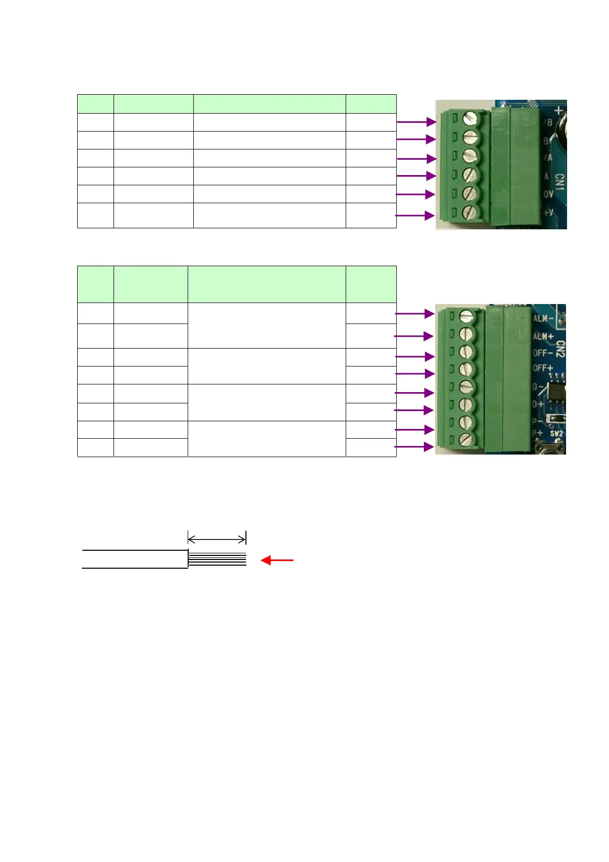
3-2 CN2
No.
Signal
name
Definition
IN/OUT
8
ALM-
Power element overheat
alarm. (OFF at Alarm)
OUT
7
ALM+
OUT
6
OFF-
Input Excitation OFF
IN
5
OFF+
IN
4
D-
Input Direction Command or
CCW pulse
IN
3
D+
IN
2
P-
Input Command pulse or CW
pulse
IN
1
P+
IN
Applicable terminal block: MC1.5/8-ST-3.5 (Phoenix contact)
Note 1) Be careful not to mistake the pin number especially for power supply and motor wiring.
Note 2) Applicable wire size: AWG 28 to AWG 16 (stranded wire)
The length of the stripped bare wire: 6 to 7mm
6 to 7mm
Do not pre-solder to the wire tip!
(You will not be able to wire
connection correctly.)

Table of Contents

Questions and Answers:

Question and Answer IconNeed help?

Do you have a question about the HPtec SD4030B3 and is the answer not in the manual?

HPtec SD4030B3 Specifications

General IconGeneral
BrandHPtec
ModelSD4030B3
CategoryControl Unit
LanguageEnglish