GEO416 - GEO416GS
EN - 15
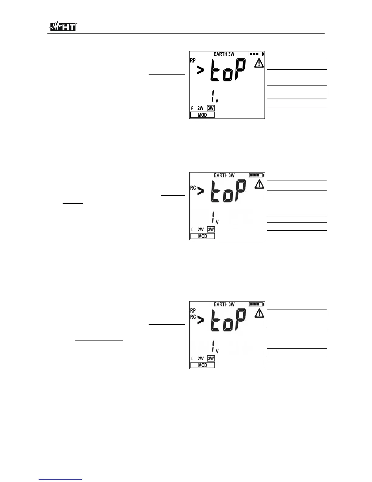
4.5.1. Anomalous measuring applications
1. When starting a measurement the
instrument checks the continuity of
measuring cables. If the volt circuit
(red cable S and green cable ES) is
interrupted or its resistance value is
too high, the instrument displays a
screen similar to the one beside. Check
that terminals are properly connected
and that the earth rod is connected to
Volt circuit’s resistance too
hi
h
Value of input interfering
voltage
Example for 3W mode
terminal S and not driven into a pebbly or scarcely conductive ground. In this latter
case pour water around the rod to decrease its resistance value (§ 11.2).
RP>top is displayed when:
The S rod’s resistance RS > 50KΩ is summed up to the volt circuit
The resistance of rod S exceeds the value 1200 + 100 RX [Ω] (where RX is the
earth resistance value)
2. When starting a measurement the
instrument checks the continuity of
measuring cables. If the ampere
circuit (blue cable H and black cable
E) is interrupted or its resistance
value is too high, the instrument
displays a screen similar to the one
beside. Check that terminals are
properly connected and that the earth
rod is connected to
Ampere circuit’s resistance
too hi
h
Value of input interfering
voltage
Example for 3W mode
terminal H and not driven into a pebbly or scarcely conductive ground. In this latter
case pour water around the rod to decrease its resistance value (§ 11.2).
RC>top is displayed when:
The H rod’s resistance RH > 50KΩ is summed up to the ampere circuit
The resistance of rod H exceeds the value 1200 + 100 R
X [Ω] (where RX is the
earth resistance value)
3. When starting a measurement the
instrument checks the continuity of
measuring cables. If the volt circuit
(red cable S and green cable ES) and
the ampere circuit (blue cable H and
black cable E) are both interrupted or
their resistance values are too high,
the instrument displays a screen similar
to the one beside. Check that the
Both volt and ampere
circuits’ resistance too hi
h
Value of input interfering
voltage
Example for 3W mode
terminals are properly connected and that the earth rods connected to terminals S
and H are not driven into a pebbly or scarcely conductive ground. In this latter case
pour water around the rods to decrease their resistance value (§ 11.2).
RP, RC>top is displayed when:
The S rod’s resistance RS > 50KΩ is summed up to the volt circuit and the H
rod’s resistance H R
H > 50KΩ is summed up to the ampere circuit
Both the S rod’s resistance and the H rod’s resistance exceed the value 1200 +
100 RX [Ω] (where RX is the earth resistance value)