GEO416 - GEO416GS
EN - 26
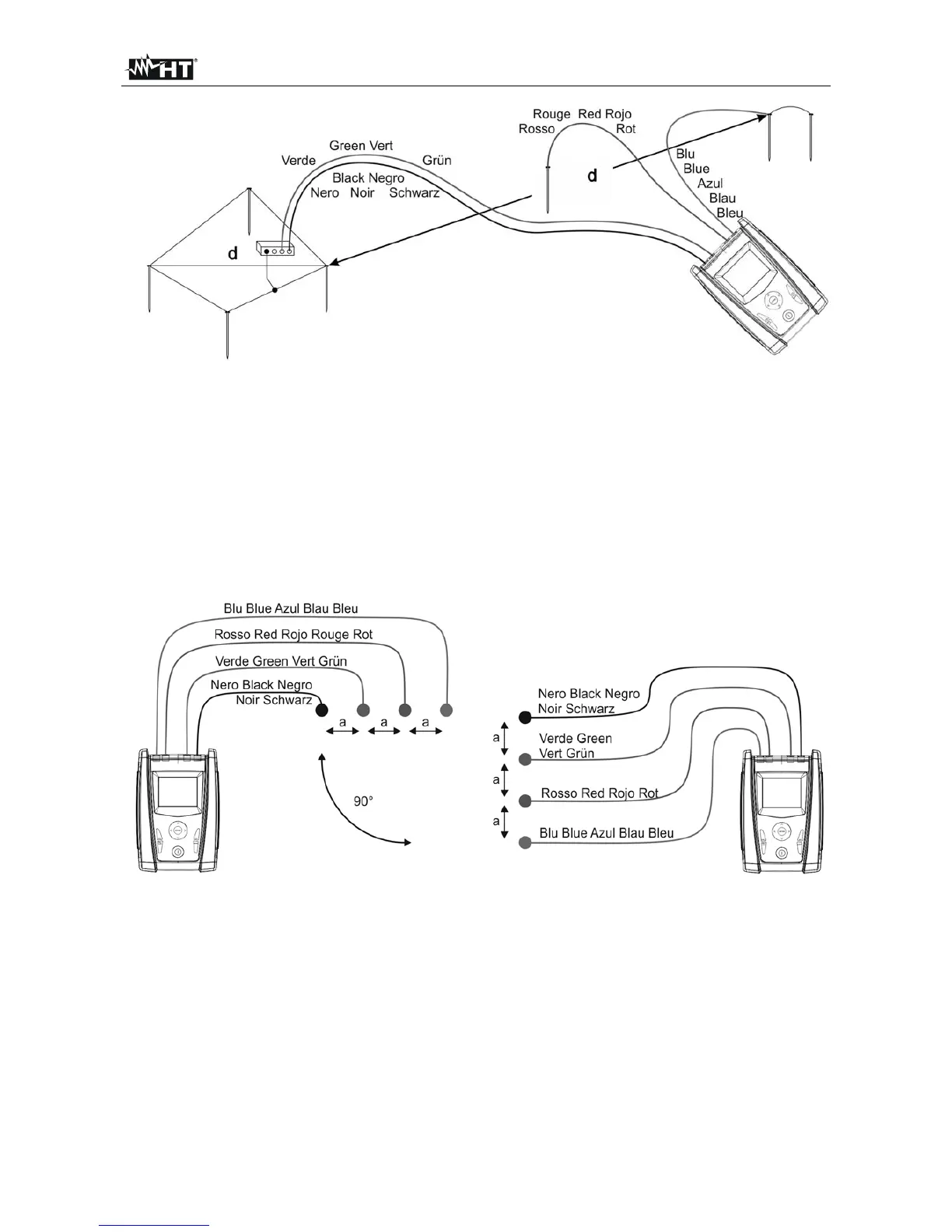
Fig. 8: Earth resistance measurement – large-sized earth rods
11.3. GROUND RESISTIVITY
This test aims at analyzing the resistivity value of the ground in order to define the type of
rods to be used when designing the installation. For the resistivity test correct or not
correct values do not exist. The various values measured by positioning the rods at
growing distances “a” must be quoted in a graph. According to the resulting curve, suitable
rods will be chosen. As the test result can be affected by metal parts buried such as pipes,
cables or other rods etc., it is advisable in case of doubts to take a second measurement
positioning the rods at an equal distance "a", but rotating their axis by 90°.
Fig. 9: Measurement of ground resistivity
The resistivity value is given by the following relation:
E
= 2 a R where:
E
= ground resistivity
a = distance between probes [m]
R = resistance measured by the instrument []